Ensure ideal temperature and humidity conditions for your well-being using HDC2010 and PIC18F4515
The secret to ideal living!

Published Nov 07, 2023
Click board™
Temp&Hum 3 click
Dev. board
EasyPIC v7
Compiler
NECTO Studio
MCU
PIC18F4515
Experience effortless comfort with our solution that maintains the perfect temperature and humidity levels
A
A
Hardware Overview
How does it work?
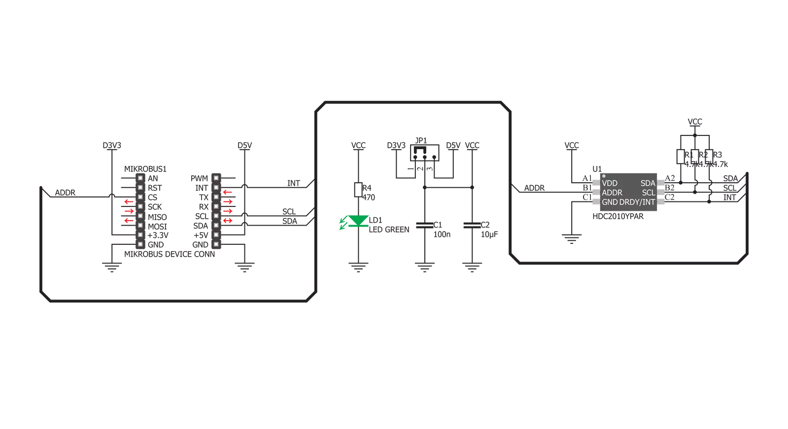
Temp&Hum 3 Click is based on the HDC2010, a low-power humidity and temperature digital sensor from Texas Instruments. This sensor is factory calibrated to 2% relative humidity and 0.2°C temperature accuracy. It has an integrated heating element that is used to evaporate condensation, protecting the sensor that way. This heating element can be simply activated by setting a bit in the appropriate register. In the case when the heater is powered on, the power consumption might rise to about 130mA. Internally, two sensors are connected to the ADC section, which can be set to sample measurements with the resolution of 9, 11 or 14 bits, based on the measurement time. The OTP memory holds the calibration coefficients that are applied to the measured value and the results are stored on the output registers, in the MSB/LSB format. These values are then used in formulas found in the HDC2010 datasheet so that the final temperature or relative humidity data can be
calculated. It is also possible to correct the offsets with custom values. HDC2010 IC uses the I2C protocol to communicate with the host MCU. Its I2C bus pins are routed to the mikroBUS™ I2C pins and are pulled to a HIGH logic level by the onboard resistors. The ADDR pin of the HDC2010 is routed to the CS pin of the mikroBUS™ and it represents the least significant bit of the I2C address. The final I2C address of this IC is determined by setting this pin either to a HIGH logic level for 1, or a LOW logic level for 0. Temp&Hum 3 click supports programmable interrupt engine, saving the host MCU from having to constantly poll the IC for data. An interrupt signal with a selectable polarity and behavior can be generated on the DRDY/INT pin of the HDC2010. It can be triggered by several event sources: it can be triggered by the temperature Lo/Hi threshold events, Humidity Lo/Hi events, as well as the readiness status of the measurement data. Setting up the interrupts can be
achieved by programming the appropriate IC registers via the I2C bus. More information about these registers can be found in the HDC2010 datasheet. HDC2010 IC itself is a very low power consuming device and it can work in two modes: sleep and active (measurement) mode. The device enters the sleep the mode as soon possible, to save power. While in the active mode, measurement can be either automatic with predefined output data rate (ODR) or on-demand. In the automatic mode, the measurement is triggered in predefined time segments, while on-demand measurement happens whenever the I2C command is sent. As soon as the single measurement is finished, the device falls back to a sleep mode. Onboard SMD jumper is used to select the power supply voltage. This allows Temp&Hum 3 click to be used with both 3.3V and 5V MCUs.

Features overview
Development board
EasyPIC v7 is the seventh generation of PIC development boards specially designed to develop embedded applications rapidly. It supports a wide range of 8-bit PIC microcontrollers from Microchip and has a broad set of unique functions, such as a powerful onboard mikroProg programmer and In-Circuit debugger over USB-B. The development board is well organized and designed so that the end-user has all the necessary elements in one place, such as switches, buttons, indicators, connectors, and others. With four different connectors for each port, EasyPIC v7 allows you to connect accessory boards, sensors, and custom electronics more efficiently than ever. Each part of
the EasyPIC v7 development board contains the components necessary for the most efficient operation of the same board. An integrated mikroProg, a fast USB 2.0 programmer with mikroICD hardware In-Circuit Debugger, offers many valuable programming/debugging options and seamless integration with the Mikroe software environment. Besides it also includes a clean and regulated power supply block for the development board. It can use various external power sources, including an external 12V power supply, 7-23V AC or 9-32V DC via DC connector/screw terminals, and a power source via the USB Type-B (USB-B) connector. Communication options such as
USB-UART and RS-232 are also included, alongside the well-established mikroBUS™ standard, three display options (7-segment, graphical, and character-based LCD), and several different DIP sockets. These sockets cover a wide range of 8-bit PIC MCUs, from PIC10F, PIC12F, PIC16F, PIC16Enh, PIC18F, PIC18FJ, and PIC18FK families. EasyPIC v7 is an integral part of the Mikroe ecosystem for rapid development. Natively supported by Mikroe software tools, it covers many aspects of prototyping and development thanks to a considerable number of different Click boards™ (over a thousand boards), the number of which is growing every day.

Microcontroller Overview
MCU Card / MCU
Architecture
PIC
MCU Memory (KB)
48
Silicon Vendor
Microchip
Pin count
40
RAM (Bytes)
3968
Used MCU Pins
mikroBUS™ mapper
Take a closer look
Click board™ Schematic
Step by step
Project assembly

Start by selecting your development board and Click board™. Begin with the EasyPIC v7 as your development board.


Track your results in real time
Application Output
1. Application Output - In Debug mode, the 'Application Output' window enables real-time data monitoring, offering direct insight into execution results. Ensure proper data display by configuring the environment correctly using the provided tutorial.

2. UART Terminal - Use the UART Terminal to monitor data transmission via a USB to UART converter, allowing direct communication between the Click board™ and your development system. Configure the baud rate and other serial settings according to your project's requirements to ensure proper functionality. For step-by-step setup instructions, refer to the provided tutorial.

3. Plot Output - The Plot feature offers a powerful way to visualize real-time sensor data, enabling trend analysis, debugging, and comparison of multiple data points. To set it up correctly, follow the provided tutorial, which includes a step-by-step example of using the Plot feature to display Click board™ readings. To use the Plot feature in your code, use the function: plot(*insert_graph_name*, variable_name);. This is a general format, and it is up to the user to replace 'insert_graph_name' with the actual graph name and 'variable_name' with the parameter to be displayed.

Software Support
Library Description
This library contains API for Temp&Hum 3 Click driver.
Key functions:
temphum3_get_temperature- Get temperature valuetemphum3_get_huminidy- Get temperature valuetemphum3_get_max_hum- Get maximum temperature value
Open Source
Code example
The complete application code and a ready-to-use project are available through the NECTO Studio Package Manager for direct installation in the NECTO Studio. The application code can also be found on the MIKROE GitHub account.
/*!
 * \file
 * \brief TempHum 3 Click example
 *
 * # Description
 * This application reads temperature and humidity data.
 *
 * The demo application is composed of two sections :
 *
 * ## Application Init
 * Initializes the driver and performs the Click default configuration.
 *
 * ## Application Task
 * Reads the temperature and huminidy and logs results to the USB UART every 500 ms.
 *
 * \author Petar Suknjaja
 *
 */
#include "board.h"
#include "log.h"
#include "temphum3.h"

static temphum3_t temphum3;
static log_t logger;

void application_init ( void )
{
    log_cfg_t log_cfg;
    temphum3_cfg_t temphum3_cfg;

    /**
     * Logger initialization.
     * Default baud rate: 115200
     * Default log level: LOG_LEVEL_DEBUG
     * @note If USB_UART_RX and USB_UART_TX
     * are defined as HAL_PIN_NC, you will
     * need to define them manually for log to work.
     * See @b LOG_MAP_USB_UART macro definition for detailed explanation.
     */
    LOG_MAP_USB_UART( log_cfg );
    log_init( &logger, &log_cfg );
    log_info( &logger, " Application Init " );

    //  Click initialization.
    temphum3_cfg_setup( &temphum3_cfg );
    TEMPHUM3_MAP_MIKROBUS( temphum3_cfg, MIKROBUS_1 );
    if ( I2C_MASTER_ERROR == temphum3_init( &temphum3, &temphum3_cfg ) )
    {
        log_error( &logger, " Communication init." );
        for ( ; ; );
    }

    temphum3_default_cfg( &temphum3 );

    log_info( &logger, " Application Task " );
}

void application_task ( void )
{
    float temperature = 0;
    float humidity = 0;

    temperature = temphum3_get_temperature( &temphum3 );
    log_printf( &logger, " Temperature : %.2f C \r\n", temperature );

    humidity = temphum3_get_humidity( &temphum3 );
    log_printf( &logger, " Humidity : %.1f %% \r\n", humidity );
    Delay_ms ( 500 );
}

int main ( void )
{
    /* Do not remove this line or clock might not be set correctly. */
    #ifdef PREINIT_SUPPORTED
    preinit();
    #endif

    application_init( );

    for ( ; ; )
    {
        application_task( );
    }

    return 0;
}

// ------------------------------------------------------------------------ END
Additional Support
Resources
Category:Temperature & humidity


