Monitor smoke levels and conditions remotely using the MAX30105 and PIC18F45K40
Clearing the air: The future of smoke detection and prevention

Published Sep 19, 2023
Click board™
Smoke Click
Dev. board
EasyPIC v7
Compiler
NECTO Studio
MCU
PIC18F45K40
Discover how our advanced smoke detection solution enhances your ability to prevent and mitigate fire risks, creating safer environments for everyone
A
A
Hardware Overview
How does it work?
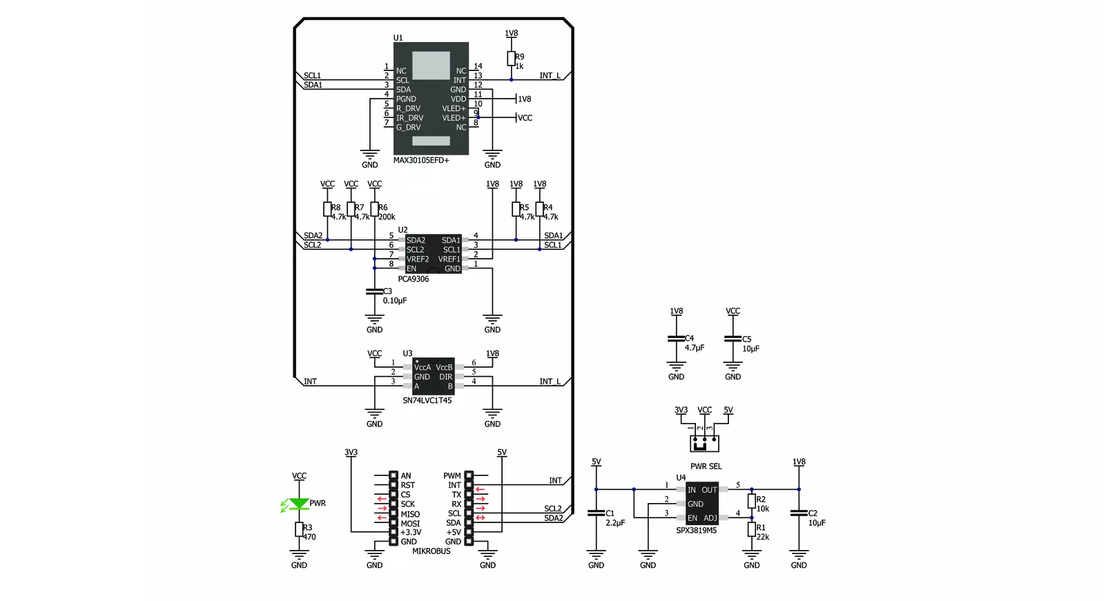
Smoke Click is based on the MAX30105, a high-sensitivity optical sensor for smoke detection applications from Analog Devices. The sensor is an integrated particle-sensing module with internal LEDs, photodetectors, optical elements, and low-noise electronics with ambient light rejection. To detect the smoke, the MAX30105 senses the light of LEDs that are rejected from the smoke particles by the photodetectors. The particle-sensing subsystem contains ambient light cancellation (ALC), a continuous-time sigma-delta 18-bit ADC, and a proprietary discrete time filter. The ALC has an internal track/hold circuit to cancel ambient light and increase dynamic range. The ADC output data rate can be programmed from 50sps to 3200sps. The MAX30105 integrates red, green, and IR LED drivers to modulate LED pulses for
particle-sensing measurements. The LED current can be programmed from 0 up to 50mA. The onboard temperature sensor is used for calibrating the temperature dependence of the particle-sensing subsystem. This temperature sensor has an inherent resolution of 0.0625°C. After the particle-sensing initiation, the IR LED is activated in proximity mode; when an object is detected, it goes automatically to the normal mode. The proximity mode can be re-entered. Smoke Click uses a standard 2-Wire I2C interface to communicate with the host MCU, supporting the clock data rates up to 400KHz. The sensor uses 1.8V for a power supply, which on this Click board™ is available over the SPX3819MS, a 500mA low-noise LDO voltage regulator from MaxLinear. For this sensor to work with higher logic levels,
Smoke Click features the PCA9306, a dual bidirectional I2C bus, and an SMBus voltage-level translator from Texas Instruments. One of the available interrupt statuses can be received over the INT pin and the SN74LVC1T45, a single-bit dual-supply bus transceiver with configurable voltage translation and 3-state outputs from Texas Instruments. This Click board™ can operate with either 3.3V or 5V logic voltage levels selected via the PWR SEL jumper. This way, both 3.3V and 5V capable MCUs can use the communication lines properly. Also, this Click board™ comes equipped with a library containing easy-to-use functions and an example code that can be used as a reference for further development.


Features overview
Development board
EasyPIC v7 is the seventh generation of PIC development boards specially designed to develop embedded applications rapidly. It supports a wide range of 8-bit PIC microcontrollers from Microchip and has a broad set of unique functions, such as a powerful onboard mikroProg programmer and In-Circuit debugger over USB-B. The development board is well organized and designed so that the end-user has all the necessary elements in one place, such as switches, buttons, indicators, connectors, and others. With four different connectors for each port, EasyPIC v7 allows you to connect accessory boards, sensors, and custom electronics more efficiently than ever. Each part of
the EasyPIC v7 development board contains the components necessary for the most efficient operation of the same board. An integrated mikroProg, a fast USB 2.0 programmer with mikroICD hardware In-Circuit Debugger, offers many valuable programming/debugging options and seamless integration with the Mikroe software environment. Besides it also includes a clean and regulated power supply block for the development board. It can use various external power sources, including an external 12V power supply, 7-23V AC or 9-32V DC via DC connector/screw terminals, and a power source via the USB Type-B (USB-B) connector. Communication options such as
USB-UART and RS-232 are also included, alongside the well-established mikroBUS™ standard, three display options (7-segment, graphical, and character-based LCD), and several different DIP sockets. These sockets cover a wide range of 8-bit PIC MCUs, from PIC10F, PIC12F, PIC16F, PIC16Enh, PIC18F, PIC18FJ, and PIC18FK families. EasyPIC v7 is an integral part of the Mikroe ecosystem for rapid development. Natively supported by Mikroe software tools, it covers many aspects of prototyping and development thanks to a considerable number of different Click boards™ (over a thousand boards), the number of which is growing every day.

Microcontroller Overview
MCU Card / MCU
Architecture
PIC
MCU Memory (KB)
32
Silicon Vendor
Microchip
Pin count
40
RAM (Bytes)
2048
Used MCU Pins
mikroBUS™ mapper
Take a closer look
Click board™ Schematic
Step by step
Project assembly

Start by selecting your development board and Click board™. Begin with the EasyPIC v7 as your development board.


Track your results in real time
Application Output
1. Application Output - In Debug mode, the 'Application Output' window enables real-time data monitoring, offering direct insight into execution results. Ensure proper data display by configuring the environment correctly using the provided tutorial.

2. UART Terminal - Use the UART Terminal to monitor data transmission via a USB to UART converter, allowing direct communication between the Click board™ and your development system. Configure the baud rate and other serial settings according to your project's requirements to ensure proper functionality. For step-by-step setup instructions, refer to the provided tutorial.

3. Plot Output - The Plot feature offers a powerful way to visualize real-time sensor data, enabling trend analysis, debugging, and comparison of multiple data points. To set it up correctly, follow the provided tutorial, which includes a step-by-step example of using the Plot feature to display Click board™ readings. To use the Plot feature in your code, use the function: plot(*insert_graph_name*, variable_name);. This is a general format, and it is up to the user to replace 'insert_graph_name' with the actual graph name and 'variable_name' with the parameter to be displayed.

Software Support
Library Description
This library contains API for Smoke Click driver.
Key functions:
smoke_set_registers- Set registers values functionsmoke_enable_disable_interrupts- Enable or disable interrupt functionsmoke_read_leds- Function for reading enabled led values
Open Source
Code example
The complete application code and a ready-to-use project are available through the NECTO Studio Package Manager for direct installation in the NECTO Studio. The application code can also be found on the MIKROE GitHub account.
/*!
 * \file
 * \brief Smoke Click example
 *
 * # Description
 * This Click includes internal LEDs, photodetectors, optical elements, and low-noise electronics
 * with ambient light rejection. The sensor can detect a wide variety of smoke particle sizes.
 * It also has an on-chip temperature sensor for calibrating the temperature dependence of the
 * particle sensing subsystem. The temperature sensor has an inherent resolution 0.0625°C.
 *
 *
 * The demo application is composed of two sections :
 *
 * ## Application Init
 * Initalizes I2C driver, applies "set registers check green values" settings,
 * "enable FIFO data ready interrupt" and makes an initial log.
 *
 * ## Application Task
 * This example demonstrates the use of Smoke Click board. It reads reflected green values and
 * temperature from an internal sensor and displays the results on USART terminal.
 * It usualy takes two or three readings in order to get corect readings. Expect big values when you do.
 *
 *
 * \author MikroE Team
 *
 */
// ------------------------------------------------------------------- INCLUDES

#include "board.h"
#include "log.h"
#include "smoke.h"

// ------------------------------------------------------------------ VARIABLES

static smoke_t smoke;
static log_t logger;

static float temperature;

// ------------------------------------------------------ APPLICATION FUNCTIONS

void application_init ( void )
{
    log_cfg_t log_cfg;
    smoke_cfg_t cfg;

    /**
     * Logger initialization.
     * Default baud rate: 115200
     * Default log level: LOG_LEVEL_DEBUG
     * @note If USB_UART_RX and USB_UART_TX
     * are defined as HAL_PIN_NC, you will
     * need to define them manually for log to work.
     * See @b LOG_MAP_USB_UART macro definition for detailed explanation.
     */
    LOG_MAP_USB_UART( log_cfg );
    log_init( &logger, &log_cfg );
    log_info( &logger, "---- Application Init ----" );

    //  Click initialization.

    smoke_cfg_setup( &cfg );
    SMOKE_MAP_MIKROBUS( cfg, MIKROBUS_1 );
    smoke_init( &smoke, &cfg );

    smoke_reset( &smoke );
    smoke_default_cfg ( &smoke );

    log_info( &logger, "---- Application Task ----" );
    Delay_ms ( 100 );
    if ( smoke_read_leds( &smoke ) != SMOKE_OK )
    {
        log_info( &logger, "---- Init Error ----" );
        for( ; ; );
    }
}

void application_task ( void )
{
    smoke_read_leds( &smoke );

    log_printf( &logger, "Red : %llu\r\n", smoke.red_value );
    log_printf( &logger, "IR : %llu\r\n", smoke.ir_value );
    log_printf( &logger, "Green : %llu\r\n", smoke.green_value );
    log_printf( &logger, "------------------------------\r\n" );

    temperature = smoke_read_temp( &smoke );

    log_printf( &logger, "Read Temperature[ degC ]: %.2f\r\n",  temperature );
    log_printf( &logger, "------------------------------\r\n" );

    Delay_ms ( 1000 );
}

int main ( void )
{
    /* Do not remove this line or clock might not be set correctly. */
    #ifdef PREINIT_SUPPORTED
    preinit();
    #endif

    application_init( );

    for ( ; ; )
    {
        application_task( );
    }

    return 0;
}


// ------------------------------------------------------------------------ END


