Experience the future of temperature management with MAX31855 and PIC18F4553
Smart thermometry for a safer world

Published Nov 08, 2023
Click board™
Thermostat 3 Click
Dev. board
EasyPIC v7
Compiler
NECTO Studio
MCU
PIC18F4553
Elevate your temperature measurement capabilities with our solution, designed to adapt to the unique demands of your industry.
A
A
Hardware Overview
How does it work?
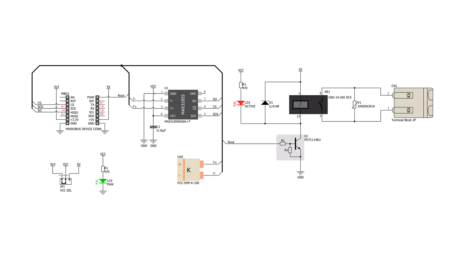
Thermostat 3 Click is based on the MAX31855, a thermocouple-to-digital converter with a built-in 14-bit analog-to-digital converter (ADC), from Analog Devices. The device also contains cold-junction compensation sensing and correction, a digital controller, a SPI compatible interface, and associated control logic. The Thermostat 3 click is designed to be used with externally connected K-type thermocouple sensor. The communication with the host MCU is performed over the SPI interface, using the dedicated pins of the mikroBUS™. Depending on the temperature information obtained over the SPI interface, the host MCU can take the necessary action: it can either open or close contacts of the relay. The Click board™ uses the G6D series PCB power relay, from Omron. This quality relay can withstand an amazingly large number of mechanical cycles, with no load connected. However, when there is a significant load connected at its output, micro-electric arcs cause the contacts to wear over time. With the maximum load current of 5A, it can sustain up to 70,000 cycles. Its contacts are made of silver alloy, yielding
exceptional ON resistance of only 100mΩ (max). The relay is activated by the host MCU. The voltage for the coil activation is 5V, while the current through the coil is 40mA. The MCU is not able to drive the coil directly, therefore an NPN transistor had to be added. Its base is controlled by the host MCU, allowing the coil to drain enough current from the 5V mikroBUS™ power rail. The base of the transistor is routed to the CS pin of the Click board™. The transistor packs two biasing resistors in the same casing, so it can be directly used on the MCU pin, without external biasing resistors. A red color LED, labeled as ACTIVE is used to indicate that the transistor is in an open state and that the current is running through the relay coil. When the current through a coil (or any other inductor) is suddenly changed, the backEMF will be generated, opposing the changes of the current. This can sometimes lead to damage to the control circuit: in this case, the transistor will become inversely polarized. To prevent this from happening, a flyback diode is added across the coil. During the normal operation, this diode does not conduct any current. However, when the coil is
switched OFF, the inverse polarization will cause the current to pass through this diode with minimum resistance. This prevents inverse (flyback) voltage from building up, so the transistor remains safe. Contacts at the output may be connected to a higher voltage and larger current may run through. To prevent high voltage transients in this case, a flyback diode is not a viable option. Therefore, Thermostat 3 click uses a varistor (VDR). This component rapidly drops its resistance as the voltage rises above its rated clamping voltage. The excessive voltage transient will pass through the VDR since it will become a current path with the least resistance. During the normal operation, while the voltage stays below the rated clamping voltage, VDR has a very high resistance, so the current runs through the electrical circuit, instead. The operating voltage of the Click board™ can be selected by the VCC SEL jumper. This jumper allows selecting either 3.3V or 5V from the mikroBUS™. The selected voltage will be applied to the VCC pin of the connected MAX31855 sensor.

Features overview
Development board
EasyPIC v7 is the seventh generation of PIC development boards specially designed to develop embedded applications rapidly. It supports a wide range of 8-bit PIC microcontrollers from Microchip and has a broad set of unique functions, such as a powerful onboard mikroProg programmer and In-Circuit debugger over USB-B. The development board is well organized and designed so that the end-user has all the necessary elements in one place, such as switches, buttons, indicators, connectors, and others. With four different connectors for each port, EasyPIC v7 allows you to connect accessory boards, sensors, and custom electronics more efficiently than ever. Each part of
the EasyPIC v7 development board contains the components necessary for the most efficient operation of the same board. An integrated mikroProg, a fast USB 2.0 programmer with mikroICD hardware In-Circuit Debugger, offers many valuable programming/debugging options and seamless integration with the Mikroe software environment. Besides it also includes a clean and regulated power supply block for the development board. It can use various external power sources, including an external 12V power supply, 7-23V AC or 9-32V DC via DC connector/screw terminals, and a power source via the USB Type-B (USB-B) connector. Communication options such as
USB-UART and RS-232 are also included, alongside the well-established mikroBUS™ standard, three display options (7-segment, graphical, and character-based LCD), and several different DIP sockets. These sockets cover a wide range of 8-bit PIC MCUs, from PIC10F, PIC12F, PIC16F, PIC16Enh, PIC18F, PIC18FJ, and PIC18FK families. EasyPIC v7 is an integral part of the Mikroe ecosystem for rapid development. Natively supported by Mikroe software tools, it covers many aspects of prototyping and development thanks to a considerable number of different Click boards™ (over a thousand boards), the number of which is growing every day.

Microcontroller Overview
MCU Card / MCU
Architecture
PIC
MCU Memory (KB)
32
Silicon Vendor
Microchip
Pin count
40
RAM (Bytes)
2048
You complete me!
Accessories
The Type-K thermocouple, equipped with glass braid insulation, is a versatile tool designed for precision temperature measurements, particularly in high-temperature environments. With a calibrated Type-K configuration and a 24 AWG gage wire spanning 2 meters, this probe is engineered to provide reliable readings. Its operational temperature range extends to 480°C (900°F), making it suitable for demanding applications. The glass braid insulation ensures durability and stability during measurements, and the connector body can withstand temperatures up to 220°C (425°F). The Type-K thermocouple probe features a PCC-SMP connector at its end, which offers compatibility with THERMO Click and Thermo K Click boards. This connectivity makes it a valuable tool for various industrial and scientific settings, where precision and reliability in temperature monitoring are essential.

Used MCU Pins
mikroBUS™ mapper
Take a closer look
Click board™ Schematic
Step by step
Project assembly

Start by selecting your development board and Click board™. Begin with the EasyPIC v7 as your development board.


Track your results in real time
Application Output
1. Application Output - In Debug mode, the 'Application Output' window enables real-time data monitoring, offering direct insight into execution results. Ensure proper data display by configuring the environment correctly using the provided tutorial.

2. UART Terminal - Use the UART Terminal to monitor data transmission via a USB to UART converter, allowing direct communication between the Click board™ and your development system. Configure the baud rate and other serial settings according to your project's requirements to ensure proper functionality. For step-by-step setup instructions, refer to the provided tutorial.

3. Plot Output - The Plot feature offers a powerful way to visualize real-time sensor data, enabling trend analysis, debugging, and comparison of multiple data points. To set it up correctly, follow the provided tutorial, which includes a step-by-step example of using the Plot feature to display Click board™ readings. To use the Plot feature in your code, use the function: plot(*insert_graph_name*, variable_name);. This is a general format, and it is up to the user to replace 'insert_graph_name' with the actual graph name and 'variable_name' with the parameter to be displayed.

Software Support
Library Description
This library contains API for Thermostat 3 Click driver.
Key functions:
thermostat3_relay_control- This function enables control of the relay.thermostat3_get_fault_data- This function returns Fault data Value.thermostat3_get_thermocouple_temperature- This function returns 14-Bit Thermocouple Temperature Data
Open Source
Code example
The complete application code and a ready-to-use project are available through the NECTO Studio Package Manager for direct installation in the NECTO Studio. The application code can also be found on the MIKROE GitHub account.
/*!
 * \file
 * \brief Thermostat3 Click example
 *
 * # Description
 * This application enables usage of the general puprose Thermostat Click to be used with temperature sensors.
 *
 * The demo application is composed of two sections :
 *
 * ## Application Init
 * Initialization driver init
 *
 * ## Application Task
 * Waits for valid user input and executes functions based on set of valid commands
 *
 * *note:*
 * - Additional Functions :
 *      -void _displayFault( uint8_t f_error )  - Display fault
 *
 * \author MikroE Team
 *
 */
// ------------------------------------------------------------------- INCLUDES

#include "board.h"
#include "log.h"
#include "thermostat3.h"

// ------------------------------------------------------------------ VARIABLES

static thermostat3_t thermostat3;
static temp_vals_t temp_val;
static log_t logger;

// ------------------------------------------------------- ADDITIONAL FUNCTIONS

static void display_fault ( uint8_t f_error )
{
    switch ( f_error )
    {
        case 3:
        {
            log_printf( &logger, "# Active - Fault flag " );
            break;
        }
        case 2:
        {
            log_printf( &logger, "# SCV - Fault flag " );
            break;
        }
        case 1:
        {
            log_printf( &logger,"# SCG - Fault flag " );
            break;
        }
        case 0:
        {
            log_printf( &logger,"# OC - Fault flag " );
            break;
        }
    }
}

// ------------------------------------------------------ APPLICATION FUNCTIONS

void application_init ( void )
{
    log_cfg_t log_cfg;
    thermostat3_cfg_t cfg;

    /**
     * Logger initialization.
     * Default baud rate: 115200
     * Default log level: LOG_LEVEL_DEBUG
     * @note If USB_UART_RX and USB_UART_TX
     * are defined as HAL_PIN_NC, you will
     * need to define them manually for log to work.
     * See @b LOG_MAP_USB_UART macro definition for detailed explanation.
     */
    LOG_MAP_USB_UART( log_cfg );
    log_init( &logger, &log_cfg );
    log_info( &logger, "---- Application Init ----" );

    Delay_ms ( 100 );

    //  Click initialization.

    thermostat3_cfg_setup( &cfg );
    THERMOSTAT3_MAP_MIKROBUS( cfg, MIKROBUS_1 );
    thermostat3_init( &thermostat3, &cfg );

    // Power on delay
    Delay_ms ( 200 );
    log_printf( &logger, "---- Start Thermostat 3 ----\r\n" );
}

void application_task ( void )
{
    //  Task implementation.

    float internal_temp;
    float thermocouple_temp;

    thermostat3_process( &thermostat3, &temp_val );

    internal_temp = thermostat3_get_internal_temperature( &temp_val, THERMOSTAT3_TEMP_IN_CELSIUS );
    log_printf( &logger, "# Internal Temperature: %.2f", internal_temp );
    Delay_ms ( 200 );

    thermocouple_temp = thermostat3_get_thermocouple_temperature( &temp_val, THERMOSTAT3_TEMP_IN_CELSIUS );
    log_printf( &logger, "# Thermocouple Temperature: %.2f", thermocouple_temp );
    Delay_ms ( 200 );

    if( thermostat3.relay_flag == 1)
    {
        thermostat3.relay_flag = 0;
        thermostat3_relay_control( &thermostat3, THERMOSTAT3_RELAY_OFF );
        log_printf( &logger, "# Relay OFF\r\n" );
    }
    else
    {
        thermostat3.relay_flag = 1;
        thermostat3_relay_control( &thermostat3, THERMOSTAT3_RELAY_ON );
        log_printf( &logger, "# Relay ON\r\n" );
    }
    Delay_ms ( 200 );

    if( thermostat3.fault_flag == 1 )
    {
        thermostat3.fault_flag = 0;
        log_printf( &logger, "# Fault status -- OFF\r\n" );
    }
    else
    {
        thermostat3.fault_flag = 1;
        log_printf( &logger, "# Fault status -- ON\r\n" );
    }
    Delay_ms ( 200 );

    if( thermostat3.fault_flag == 1 )
        {
            thermostat3.f_error++;
            if( thermostat3.f_error > 3 )
            {
                thermostat3.f_error = 0;
            }
            display_fault( thermostat3.f_error );

            thermostat3.fault_status = thermostat3_get_fault_data( &temp_val, 0x01 << thermostat3.f_error );

            if ( thermostat3.fault_status == 1 )
            {
                log_printf( &logger, " -- ERROR\r\n" );
            }
            else
            {
                log_printf( &logger, " -- OK\r\n" );
            }
        }
}
int main ( void )
{
    /* Do not remove this line or clock might not be set correctly. */
    #ifdef PREINIT_SUPPORTED
    preinit();
    #endif

    application_init( );

    for ( ; ; )
    {
        application_task( );
    }

    return 0;
}


// ------------------------------------------------------------------------ END


