Develop advanced IoT projects for automation, monitoring, and control with TCM 515Z and PIC18F45K40
Communication based on the 2.4 GHz IEEE 802.15.4 radio standard

Published Jul 28, 2023
Click board™
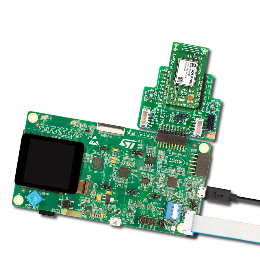
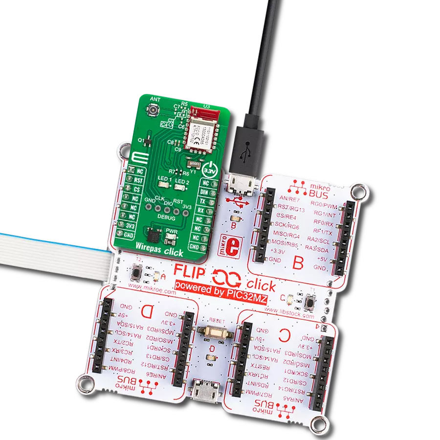
EnOcean 2 Click
Dev. board
EasyPIC v7
Compiler
NECTO Studio
MCU
PIC18F45K40
For developers working on innovative, environmentally friendly, wireless applications in home automation, industrial control, and smart building projects
A
A
Hardware Overview
How does it work?
EnOcean 2 Click is based on the TCM 515Z, a bidirectional transceiver gateway from EnOcean. Z in marking stands for a Zigbee, which uses a worldwide available 2.4GHz frequency and provides a transparent radio link between EnOcean 2.4 GHz devices and an external host connected via the standardized ESP3 interface (EnOcean SerialProtocol V3). The module has low current consumption for receiving and transmitting modes with a typical receiving sensitivity of -95dBm over the onboard 2.4GHz 50ohm whip antenna. It generates its electrical energy by converting electromagnetic, solar, and thermoelectric energy to work as a battery-free self-powered device. The TCM 515Z module supports all radio channels of the IEEE 802.15.4 standard, from 11 to channel 26 (the highest frequency). The channel can be set by
a host MCU. TCM 515Z transmits and receives radio telegrams, while the host MCU is responsible for the proper decoding of received telegrams and proper encoding of telegrams to be transmitted. The frame structure consists of PHY Header, MAC Header, MAC Payload, and AMC Trailer. The TCM 515Z module can work in the Receive and Transmit modes and be set into a low-power sleep mode for a defined period. Depending on the usage scenes, it can achieve a range of up to 50m in open spaces, halls, and more. In corridors, plasterboard, or wood walls, it can achieve typically 15m of range. The fire-safety walls, elevator shafts, staircases, and similar areas act as shielded areas. The angle at which the transmitted signal hits the wall is very important, along with the effective wall thickness, and should be considered when
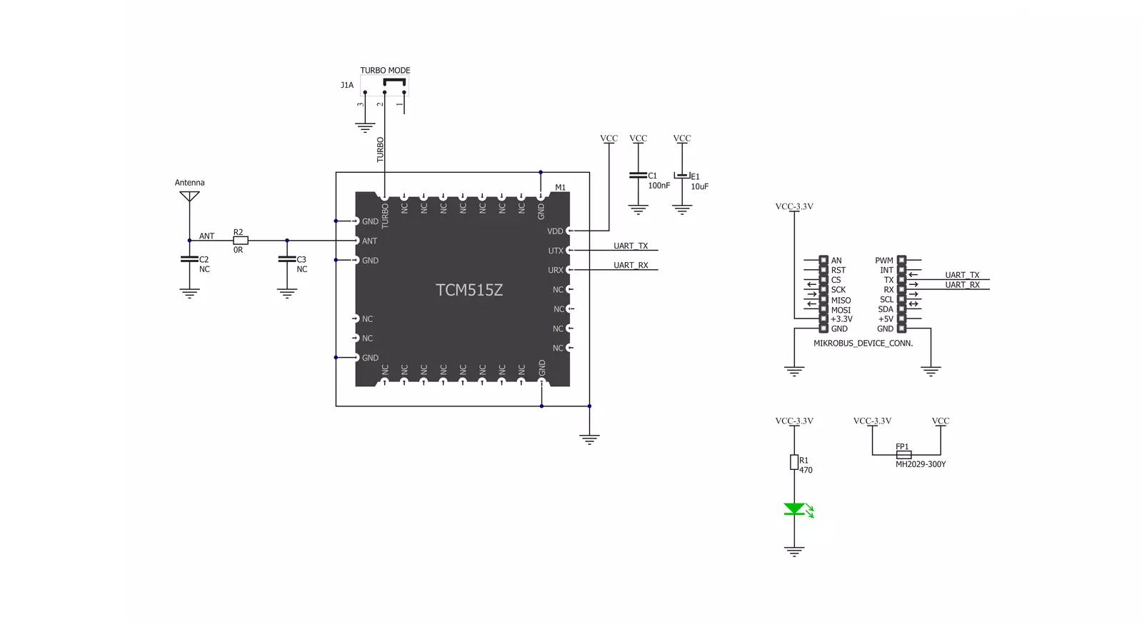
choosing the place to position the device. The EnOcean module uses the UART interface with commonly used UART RX and TX pins as its default communication protocol for communication with the host microcontroller. Additionally, changing the default ESP3 interface speed at power up from 57600 bits per second to 460800 bits per second over the TURBO jumper by connecting the 0ohm resistor to EN position. This Click board™ can be operated only with a 3.3V logic voltage level. The board must perform appropriate logic voltage level conversion before using MCUs with different logic levels. However, the Click board™ comes equipped with a library containing functions and an example code that can be used as a reference for further development.

Features overview
Development board
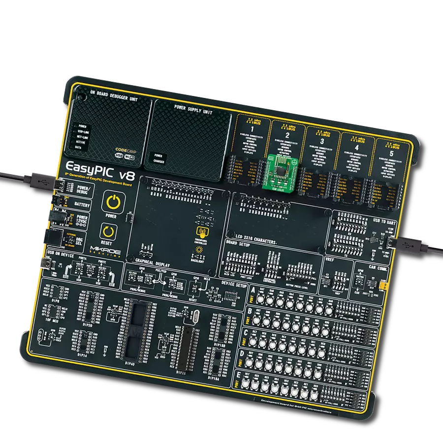
EasyPIC v7 is the seventh generation of PIC development boards specially designed to develop embedded applications rapidly. It supports a wide range of 8-bit PIC microcontrollers from Microchip and has a broad set of unique functions, such as a powerful onboard mikroProg programmer and In-Circuit debugger over USB-B. The development board is well organized and designed so that the end-user has all the necessary elements in one place, such as switches, buttons, indicators, connectors, and others. With four different connectors for each port, EasyPIC v7 allows you to connect accessory boards, sensors, and custom electronics more efficiently than ever. Each part of
the EasyPIC v7 development board contains the components necessary for the most efficient operation of the same board. An integrated mikroProg, a fast USB 2.0 programmer with mikroICD hardware In-Circuit Debugger, offers many valuable programming/debugging options and seamless integration with the Mikroe software environment. Besides it also includes a clean and regulated power supply block for the development board. It can use various external power sources, including an external 12V power supply, 7-23V AC or 9-32V DC via DC connector/screw terminals, and a power source via the USB Type-B (USB-B) connector. Communication options such as
USB-UART and RS-232 are also included, alongside the well-established mikroBUS™ standard, three display options (7-segment, graphical, and character-based LCD), and several different DIP sockets. These sockets cover a wide range of 8-bit PIC MCUs, from PIC10F, PIC12F, PIC16F, PIC16Enh, PIC18F, PIC18FJ, and PIC18FK families. EasyPIC v7 is an integral part of the Mikroe ecosystem for rapid development. Natively supported by Mikroe software tools, it covers many aspects of prototyping and development thanks to a considerable number of different Click boards™ (over a thousand boards), the number of which is growing every day.

Microcontroller Overview
MCU Card / MCU
Architecture
PIC
MCU Memory (KB)
32
Silicon Vendor
Microchip
Pin count
40
RAM (Bytes)
2048
Used MCU Pins
mikroBUS™ mapper
Take a closer look
Click board™ Schematic
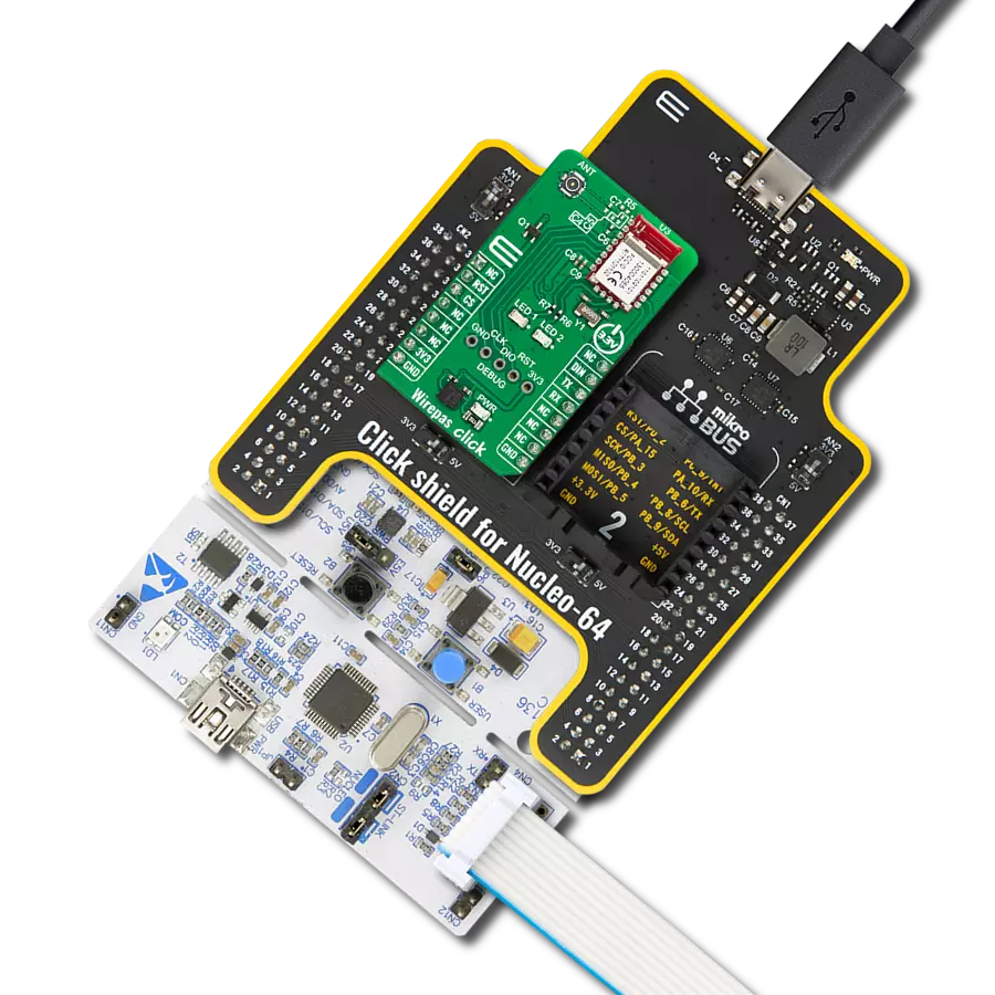
Step by step
Project assembly

Start by selecting your development board and Click board™. Begin with the EasyPIC v7 as your development board.


Software Support
Library Description
This library contains API for EnOcean 2 Click driver.
Key functions:
enocean2_init_rx_buff- EnOcean Serial Protocol ( ESP3 ) module initializationenocean2_rx- The function push recieved character to ring bufferenocean2_packet_recieve- Implements state machine for recieving packets. It should be called in loop
Open Source
Code example
The complete application code and a ready-to-use project are available through the NECTO Studio Package Manager for direct installation in the NECTO Studio. The application code can also be found on the MIKROE GitHub account.
/*!
 * \file
 * \brief EnOcean2 Click example
 *
 * # Description
 * This example reads and processes data from EnOcean 2 Clicks.
 *
 * The demo application is composed of two sections :
 *
 * ## Application Init
 * Initializes driver init and initializes chip and sets callback handler.
 *
 * ## Application Task
 * It checks if a switch is pressed, and logs an appropriate message to the uart terminal.
 *
 * ## Additional Function
 * - enocean2_process ( ) - The general process of collecting data the module sends.
 * - callback_handler ( enocean2_packet_t *packet ) - Checks if a new response message is
 *                      ready and executes a response message parsing. Once the response
 *                      parsing is done, shows the response message on the uart terminal.
 * - decode_command ( uint8_t cmd ) - Detect which of the 4 buttons is pressed.
 *
 *
 * \author MikroE Team
 *
 */
// ------------------------------------------------------------------- INCLUDES

#include "board.h"
#include "log.h"
#include "enocean2.h"
#include "string.h"

#define PROCESS_COUNTER 10
#define PROCESS_RX_BUFFER_SIZE 200

// ------------------------------------------------------------------ VARIABLES

static enocean2_t enocean2;
static enocean2_ring_buffer_t enocean2_rb;
static enocean2_rx_data_t enocean2_rx_data;
static log_t logger;

uint8_t rx_buffer[ PROCESS_RX_BUFFER_SIZE ] = { 0 };
uint8_t data_buffer[ PROCESS_RX_BUFFER_SIZE ] = { 0 };
char uart_rx_buffer[ PROCESS_RX_BUFFER_SIZE ] = { 0 };

// ------------------------------------------------------- ADDITIONAL FUNCTIONS

static void clear_app_buf ( void )
{
    Delay_ms ( 200 );
    enocean2_generic_read( &enocean2, uart_rx_buffer, PROCESS_RX_BUFFER_SIZE );
    memset( uart_rx_buffer, 0, PROCESS_RX_BUFFER_SIZE );
}

static void decode_command ( uint8_t cmd )
{
    if ( cmd == 0x12 )
    {
        log_printf( &logger,  "-- Button 1 detect --\r\n" );
        clear_app_buf(  );
    }
    else if ( cmd == 0x14 )
    {
        log_printf( &logger, "-- Button 2 detect --\r\n" );
        clear_app_buf(  );
    }
    else if ( cmd == 0x18 )
    {
        log_printf( &logger, "-- Button 3 detect --\r\n" );
        clear_app_buf(  );
    }
    else if ( cmd == 0x22 )
    {
        log_printf( &logger, "-- Button 4 detect --\r\n" );
        clear_app_buf(  );
    }
}

static void callback_handler ( enocean2_packet_t *packet )
{
    uint8_t sequence_number = 0;

    if ( packet->type == ENOCEAN2_TYPE_RADIO_802_15_4 )
    {
        if ( sequence_number != packet->data_buffer[ ENOCEAN2_SEQUENCE_NUMBER_OFFSET ] )
        {
            decode_command( packet->data_buffer[ ENOCEAN2_COMMAND_OFFSET ] );
        }
    }
}

static void enocean2_process ( void )
{
    int16_t rsp_size;
    uint8_t check_buf_cnt;
    uint8_t process_cnt = PROCESS_COUNTER;

    while( process_cnt != 0 )
    {
        rsp_size = enocean2_generic_read( &enocean2, uart_rx_buffer, PROCESS_RX_BUFFER_SIZE );
        if ( rsp_size > 0 )
        {
            // Validation of the received data
            for ( check_buf_cnt = 0; check_buf_cnt < rsp_size; check_buf_cnt++ )
            {
                enocean2_rx( &enocean2_rb, uart_rx_buffer[ check_buf_cnt ] );
                enocean2_packet_recieve( &enocean2, &enocean2_rb );
            }

            // Clear RX buffer
            memset( uart_rx_buffer, 0, PROCESS_RX_BUFFER_SIZE );
        }
        else
        {
            process_cnt--;

            // Process delay
            Delay_ms ( 100 );
        }
    }
}

// ------------------------------------------------------ APPLICATION FUNCTIONS

void application_init ( void )
{
    log_cfg_t log_cfg;
    enocean2_cfg_t cfg;

    /**
     * Logger initialization.
     * Default baud rate: 115200
     * Default log level: LOG_LEVEL_DEBUG
     * @note If USB_UART_RX and USB_UART_TX
     * are defined as HAL_PIN_NC, you will
     * need to define them manually for log to work.
     * See @b LOG_MAP_USB_UART macro definition for detailed explanation.
     */
    LOG_MAP_USB_UART( log_cfg );
    log_init( &logger, &log_cfg );
    log_info( &logger, "---- Application Init ----" );

    //  Click initialization.

    enocean2_cfg_setup( &cfg );
    ENOCEAN2_MAP_MIKROBUS( cfg, MIKROBUS_1 );
    enocean2_init( &enocean2, &cfg );

    enocean2_rx_data.rx_buffer   = &rx_buffer[ 0 ];
    enocean2_rx_data.rx_size     = ENOCEAN2_RX_BUFFER_SIZE;
    enocean2_rx_data.data_buffer = &data_buffer[ 0 ];
    enocean2_rx_data.data_size   = ENOCEAN2_RX_BUFFER_SIZE;

    enocean2_init_rx_buff( &enocean2, &enocean2_rb, &enocean2_rx_data );
    enocean2_set_callback_handler( &enocean2, callback_handler );
}

void application_task ( void )
{
    enocean2_process( );
}

int main ( void )
{
    /* Do not remove this line or clock might not be set correctly. */
    #ifdef PREINIT_SUPPORTED
    preinit();
    #endif

    application_init( );

    for ( ; ; )
    {
        application_task( );
    }

    return 0;
}

// ------------------------------------------------------------------------ END