See beyond the spectrum and explore the endless possibilities of color with BU27006MUC-Z and ATmega324P
Capture true colors, every time

Published Nov 09, 2023
Click board™
Color 12 Click
Dev. board
EasyAVR v7
Compiler
NECTO Studio
MCU
ATmega324P
Experience the future of color sensing with our cutting-edge solution, redefining color precision and enhancing your visual world.
A
A
Hardware Overview
How does it work?
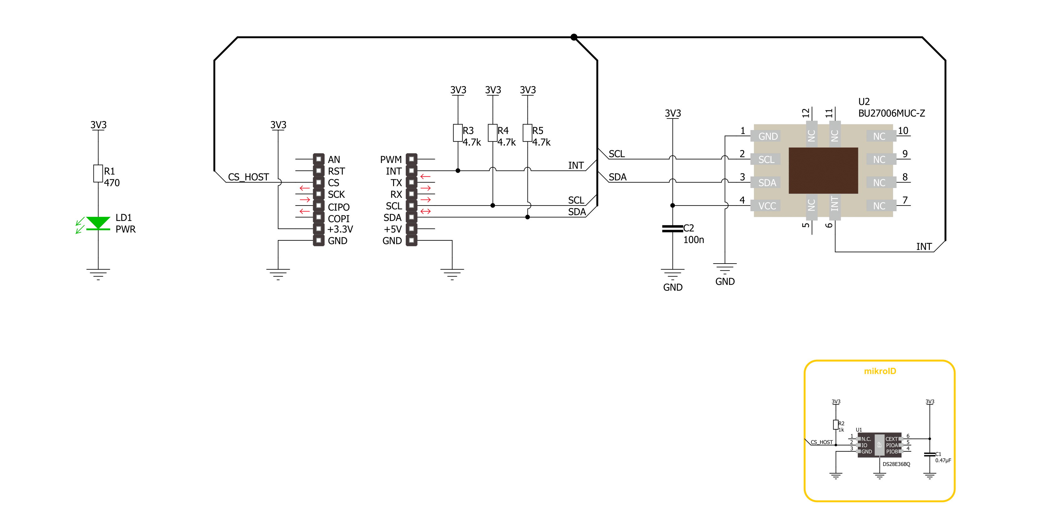
Color 12 Click is based on the BU27006MUC-Z, an advanced digital color sensor from Rohm Semiconductor with an integrated flicker sensing function. The primary purpose of this sensor is to sense Red, Green, Blue (RGB), and Infrared light and convert them into digital values via the I2C interface. The BU27006MUC-Z stands out with its exceptional performance, high sensitivity, wide dynamic range, and excellent IR-cut characteristics. These features allow for precise illuminance measurement, typically up to 50klx, with peak wavelengths for red, green, and blue of 645/575/460nm, respectively, providing accurate information about the intensity of ambient light. In addition, the BU27006MUC-Z excels at
accurately determining the ambient light's color temperature. It can effectively detect flicker noise originating from displays and room lighting, with a typical sensitivity of 10klx. This Click board™ serves various residential and commercial lighting management applications. It can be employed for contrast enhancement in various settings where optimal lighting conditions are necessary for an immersive visual experience. Moreover, the accurate detection of ambient light makes it suitable for applications that require precise backlight control, ensuring optimal visibility and energy efficiency. Color 12 Click communicates with MCU using the standard I2C 2-Wire interface to read data and configure settings, supporting
Standard Mode operation with a clock frequency of 100kHz and Fast Mode up to 400kHz. Also, it uses an interrupt pin, the INT pin of the mikroBUS™ socket, used when an interrupt occurs to alert the system when some of the results cross upper or lower threshold settings. This Click board™ can be operated only with a 3.3V logic voltage level. The board must perform appropriate logic voltage level conversion before using MCUs with different logic levels. Also, it comes equipped with a library containing functions and an example code that can be used as a reference for further development.

Features overview
Development board
EasyAVR v7 is the seventh generation of AVR development boards specially designed for the needs of rapid development of embedded applications. It supports a wide range of 16-bit AVR microcontrollers from Microchip and has a broad set of unique functions, such as a powerful onboard mikroProg programmer and In-Circuit debugger over USB. The development board is well organized and designed so that the end-user has all the necessary elements in one place, such as switches, buttons, indicators, connectors, and others. With four different connectors for each port, EasyAVR v7 allows you to connect accessory boards, sensors, and custom electronics more
efficiently than ever. Each part of the EasyAVR v7 development board contains the components necessary for the most efficient operation of the same board. An integrated mikroProg, a fast USB 2.0 programmer with mikroICD hardware In-Circuit Debugger, offers many valuable programming/debugging options and seamless integration with the Mikroe software environment. Besides it also includes a clean and regulated power supply block for the development board. It can use a wide range of external power sources, including an external 12V power supply, 7-12V AC or 9-15V DC via DC connector/screw terminals, and a power source via the USB Type-B (USB-B)
connector. Communication options such as USB-UART and RS-232 are also included, alongside the well-established mikroBUS™ standard, three display options (7-segment, graphical, and character-based LCD), and several different DIP sockets which cover a wide range of 16-bit AVR MCUs. EasyAVR v7 is an integral part of the Mikroe ecosystem for rapid development. Natively supported by Mikroe software tools, it covers many aspects of prototyping and development thanks to a considerable number of different Click boards™ (over a thousand boards), the number of which is growing every day.

Microcontroller Overview
MCU Card / MCU

Architecture
AVR
MCU Memory (KB)
32
Silicon Vendor
Microchip
Pin count
40
RAM (Bytes)
2048
Used MCU Pins
mikroBUS™ mapper
Take a closer look
Click board™ Schematic
Step by step
Project assembly

Start by selecting your development board and Click board™. Begin with the EasyAVR v7 as your development board.


Track your results in real time
Application Output
1. Application Output - In Debug mode, the 'Application Output' window enables real-time data monitoring, offering direct insight into execution results. Ensure proper data display by configuring the environment correctly using the provided tutorial.

2. UART Terminal - Use the UART Terminal to monitor data transmission via a USB to UART converter, allowing direct communication between the Click board™ and your development system. Configure the baud rate and other serial settings according to your project's requirements to ensure proper functionality. For step-by-step setup instructions, refer to the provided tutorial.

3. Plot Output - The Plot feature offers a powerful way to visualize real-time sensor data, enabling trend analysis, debugging, and comparison of multiple data points. To set it up correctly, follow the provided tutorial, which includes a step-by-step example of using the Plot feature to display Click board™ readings. To use the Plot feature in your code, use the function: plot(*insert_graph_name*, variable_name);. This is a general format, and it is up to the user to replace 'insert_graph_name' with the actual graph name and 'variable_name' with the parameter to be displayed.

Software Support
Library Description
This library contains API for Color 12 Click driver.
Key functions:
color12_get_color_data- Color 12 gets the color measurement result function.color12_set_config- Color 12 sets the configuration function.color12_get_config- Color 12 gets the configuration function.
Open Source
Code example
The complete application code and a ready-to-use project are available through the NECTO Studio Package Manager for direct installation in the NECTO Studio. The application code can also be found on the MIKROE GitHub account.
/*!
 * @file main.c
 * @brief Color 12 Click example
 *
 * # Description
 * This library contains API for the Color 12 Click driver.
 * The demo application sets sensor configuration
 * and reads and displays RGB/IR measurement results.
 *
 * The demo application is composed of two sections :
 *
 * ## Application Init
 * Initialization of I2C module and log UART.
 * After the driver init, the app executes a default configuration.
 *
 * ## Application Task
 * This example demonstrates the use of the Color 12 Click board™.
 * Reads and displays the results of the RGB/IR measurements.
 * Results are being sent to the UART Terminal, where you can track their changes.
 *
 * @author Nenad Filipovic
 *
 */

#include "board.h"
#include "log.h"
#include "color12.h"

static color12_t color12;
static log_t logger;
static uint16_t color_data;

void application_init ( void )
{
    log_cfg_t log_cfg;  /**< Logger config object. */
    color12_cfg_t color12_cfg;  /**< Click config object. */

    /**
     * Logger initialization.
     * Default baud rate: 115200
     * Default log level: LOG_LEVEL_DEBUG
     * @note If USB_UART_RX and USB_UART_TX
     * are defined as HAL_PIN_NC, you will
     * need to define them manually for log to work.
     * See @b LOG_MAP_USB_UART macro definition for detailed explanation.
     */
    LOG_MAP_USB_UART( log_cfg );
    log_init( &logger, &log_cfg );
    log_info( &logger, " Application Init " );

    // Click initialization.
    color12_cfg_setup( &color12_cfg );
    COLOR12_MAP_MIKROBUS( color12_cfg, MIKROBUS_1 );
    if ( I2C_MASTER_ERROR == color12_init( &color12, &color12_cfg ) )
    {
        log_error( &logger, " Communication init." );
        for ( ; ; );
    }

    if ( COLOR12_ERROR == color12_default_cfg ( &color12 ) )
    {
        log_error( &logger, " Default configuration." );
        for ( ; ; );
    }

    log_info( &logger, " Application Task " );
    log_printf( &logger, " ---------------------- \r\n" );
    Delay_ms ( 100 );
}

void application_task ( void )
{
    if ( COLOR12_OK == color12_get_color_data( &color12, COLOR12_DATA_RED, &color_data ) )
    {
        log_printf( &logger, " Red : %u\r\n", color_data );
    }

    if ( COLOR12_OK == color12_get_color_data( &color12, COLOR12_DATA_GREEN, &color_data ) )
    {
        log_printf( &logger, " Green : %u\r\n", color_data );
    }

    if ( COLOR12_OK == color12_get_color_data( &color12, COLOR12_DATA_BLUE, &color_data ) )
    {
        log_printf( &logger, " Blue : %u\r\n", color_data );
    }

    if ( COLOR12_OK == color12_get_color_data( &color12, COLOR12_DATA_IR, &color_data ) )
    {
        log_printf( &logger, " IR : %u\r\n", color_data );
    }
    log_printf( &logger, " ---------------------- \r\n" );
    Delay_ms ( 1000 );
}

int main ( void )
{
    /* Do not remove this line or clock might not be set correctly. */
    #ifdef PREINIT_SUPPORTED
    preinit();
    #endif

    application_init( );

    for ( ; ; )
    {
        application_task( );
    }

    return 0;
}

// ------------------------------------------------------------------------ END


