Provide precise haptic feedback for a wide array of electronic applications with DA7280 and ATmega324P
Capable of operating both linear resonant actuator (LRA) and eccentric rotating mass (ERM) actuators

Published Mar 18, 2024
Click board™
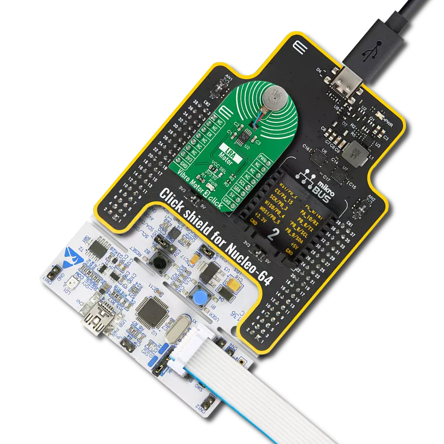
Haptic 4 Click
Dev. board
EasyAVR v7
Compiler
NECTO Studio
MCU
ATmega324P
LRA/ERM haptic driver with multiple input triggers, integrated waveform memory and wideband support
A
A
Hardware Overview
How does it work?
Haptic 4 Click is based on the DA7280, a haptic driver designed to drive linear resonant actuator (LRA) and eccentric rotating mass (ERM) actuators from Renesas. The DA7280 stands out with its automatic closed-loop LRA resonant frequency tracking feature, ensuring consistent performance across various conditions, including production tolerances and mechanical coupling effects. Depending on the register configuration, its capability to drive both LRA and ERM actuators originates from its differential output drive architecture and continuous motion sensing, which foster calibration-free operation and reduce software complexity. The DA7280's architecture is optimized for wideband operation, unlocking the full potential of the latest wideband and multidirectional LRAs. This feature makes it ideal for many applications, from wearables and electronic
peripherals to automotive, industrial settings, and AR/VR controllers. The DA7280's unique ability to control the drive level across loads connected to the OUT terminal and to sense actuator movement via a current-regulated loop and high-frequency PWM modulation enhances its utility. With support for six independent haptic sequences triggered via the mikroBUS™ pins (GP0, GP1, and GP2) without host interaction and options for external control via I2C or PWM signal, the DA7280 ensures versatile haptic feedback configurations. Using the I2C interface, this Click board™ can communicate with the host MCU supporting frequency up to 1MHz. The DA7280 is also capable of closed-loop actuator monitoring while driving to enable calibration-free playback, frequency tracking (LRA only), Active Acceleration, Rapid Stop, and actuator diagnostics available on the IRQ pin of the mikroBUS™ socket.
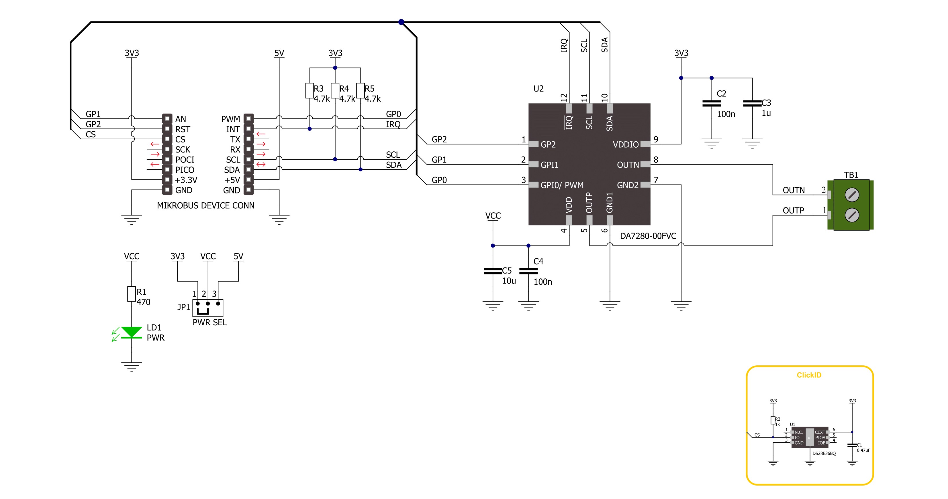
Continuous resonant frequency tracking can be enabled while driving an LRA to track the mechanical resonance of the actuator through closed-loop control. This feature maximizes electrical to mechanical energy conversion efficiency for narrowband actuators and is especially useful in applications such as operating system notifications and alarms. This Click board™ can operate with either 3.3V or 5V logic voltage levels selected via the PWR SEL jumper. This way, both 3.3V and 5V capable MCUs can use the communication lines properly. Also, this Click board™ comes equipped with a library containing easy-to-use functions and an example code that can be used as a reference for further development.

Features overview
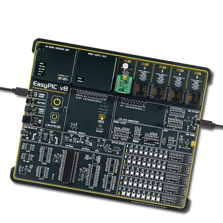
Development board
EasyAVR v7 is the seventh generation of AVR development boards specially designed for the needs of rapid development of embedded applications. It supports a wide range of 16-bit AVR microcontrollers from Microchip and has a broad set of unique functions, such as a powerful onboard mikroProg programmer and In-Circuit debugger over USB. The development board is well organized and designed so that the end-user has all the necessary elements in one place, such as switches, buttons, indicators, connectors, and others. With four different connectors for each port, EasyAVR v7 allows you to connect accessory boards, sensors, and custom electronics more
efficiently than ever. Each part of the EasyAVR v7 development board contains the components necessary for the most efficient operation of the same board. An integrated mikroProg, a fast USB 2.0 programmer with mikroICD hardware In-Circuit Debugger, offers many valuable programming/debugging options and seamless integration with the Mikroe software environment. Besides it also includes a clean and regulated power supply block for the development board. It can use a wide range of external power sources, including an external 12V power supply, 7-12V AC or 9-15V DC via DC connector/screw terminals, and a power source via the USB Type-B (USB-B)
connector. Communication options such as USB-UART and RS-232 are also included, alongside the well-established mikroBUS™ standard, three display options (7-segment, graphical, and character-based LCD), and several different DIP sockets which cover a wide range of 16-bit AVR MCUs. EasyAVR v7 is an integral part of the Mikroe ecosystem for rapid development. Natively supported by Mikroe software tools, it covers many aspects of prototyping and development thanks to a considerable number of different Click boards™ (over a thousand boards), the number of which is growing every day.

Microcontroller Overview
MCU Card / MCU

Architecture
AVR
MCU Memory (KB)
32
Silicon Vendor
Microchip
Pin count
40
RAM (Bytes)
2048
You complete me!
Accessories
Vibration ERM Motor 9K RPM 3V (VC1026B002F - old MPN C1026B002F) represents a compact-size Eccentric Rotating Mass (ERM) motor designed by Vybronics. This type of motor contains a small eccentric weight on its rotor, so while rotating, it also produces a vibration effect often used for haptic feedback on many small handheld devices. Due to its circular shape with a diameter of 10mm, the VC1026B002F is often referred to as a coin motor. The main characteristics of this vibration motor are its supply voltage, in this case, 3VDC, maximum rated current of 85mA, and the rated speed of 9000RPM, which produces the highest G force/vibration energy of 0.80GRMS. It can also be used with self-adhesive tape to mount it on your PCB or the inner wall of your product's housing.

Used MCU Pins
mikroBUS™ mapper
Take a closer look
Click board™ Schematic
Step by step
Project assembly

Start by selecting your development board and Click board™. Begin with the EasyAVR v7 as your development board.


Software Support
Library Description
This library contains API for Haptic 4 Click driver.
Key functions:
haptic4_check_communication- This function checks the communication by reading and verifying the chip IDhaptic4_set_vibration_level- This function sets the motor vibration levelhaptic4_get_vibration_level- This function reads the motor vibration level
Open Source
Code example
The complete application code and a ready-to-use project are available through the NECTO Studio Package Manager for direct installation in the NECTO Studio. The application code can also be found on the MIKROE GitHub account.
/*!
 * @file main.c
 * @brief Haptic 4 Click example
 *
 * # Description
 * This example demonstrates the use of Haptic 4 Click board by controlling
 * the attached motor vibration level.
 *
 * The demo application is composed of two sections :
 *
 * ## Application Init
 * Initializes the driver and performs the Click default configuration.
 *
 * ## Application Task
 * Changes the motor vibration level every 2 seconds between MAX and MIN,
 * and displays the currently set level on the USB UART.
 *
 * @author Stefan Ilic
 *
 */

#include "board.h"
#include "log.h"
#include "haptic4.h"

static haptic4_t haptic4;
static log_t logger;

void application_init ( void )
{
    log_cfg_t log_cfg;  /**< Logger config object. */
    haptic4_cfg_t haptic4_cfg;  /**< Click config object. */

    /**
     * Logger initialization.
     * Default baud rate: 115200
     * Default log level: LOG_LEVEL_DEBUG
     * @note If USB_UART_RX and USB_UART_TX
     * are defined as HAL_PIN_NC, you will
     * need to define them manually for log to work.
     * See @b LOG_MAP_USB_UART macro definition for detailed explanation.
     */
    LOG_MAP_USB_UART( log_cfg );
    log_init( &logger, &log_cfg );
    log_info( &logger, " Application Init " );

    // Click initialization.
    haptic4_cfg_setup( &haptic4_cfg );
    HAPTIC4_MAP_MIKROBUS( haptic4_cfg, MIKROBUS_1 );
    if ( I2C_MASTER_ERROR == haptic4_init( &haptic4, &haptic4_cfg ) )
    {
        log_error( &logger, " Communication init." );
        for ( ; ; );
    }

    if ( HAPTIC4_ERROR == haptic4_default_cfg ( &haptic4 ) )
    {
        log_error( &logger, " Default configuration." );
        for ( ; ; );
    }

    log_info( &logger, " Application Task " );
}

void application_task ( void )
{
    float vibration_level;
    if ( HAPTIC4_OK == haptic4_set_vibration_level ( &haptic4, HAPTIC4_VIBRATION_LEVEL_MAX ) )
    {
        if ( HAPTIC4_OK == haptic4_get_vibration_level ( &haptic4, &vibration_level ) )
        {
            log_printf( &logger, " Vibration level: %.3f \r\n\n", vibration_level );
        }
    }
    Delay_ms ( 1000 );
    Delay_ms ( 1000 );

    if ( HAPTIC4_OK == haptic4_set_vibration_level ( &haptic4, HAPTIC4_VIBRATION_LEVEL_MIN ) )
    {
        if ( HAPTIC4_OK == haptic4_get_vibration_level ( &haptic4, &vibration_level ) )
        {
            log_printf( &logger, " Vibration level: %.3f \r\n\n", vibration_level );
        }
    }
    Delay_ms ( 1000 );
    Delay_ms ( 1000 );
}

int main ( void )
{
    /* Do not remove this line or clock might not be set correctly. */
    #ifdef PREINIT_SUPPORTED
    preinit();
    #endif

    application_init( );

    for ( ; ; )
    {
        application_task( );
    }

    return 0;
}

// ------------------------------------------------------------------------ END