Create custom accelerometer solution based on LIS3DSH and ATmega644
Accelerate your journey: Motion sensing improved

Published Oct 02, 2023
Click board™
Accel2 Click
Dev. board
EasyAVR v7
Compiler
NECTO Studio
MCU
ATmega644
Integrate three-axis accelerometer into your solution and unlock accurate and reliable motion sensing – seize the opportunity now!
A
A
Hardware Overview
How does it work?
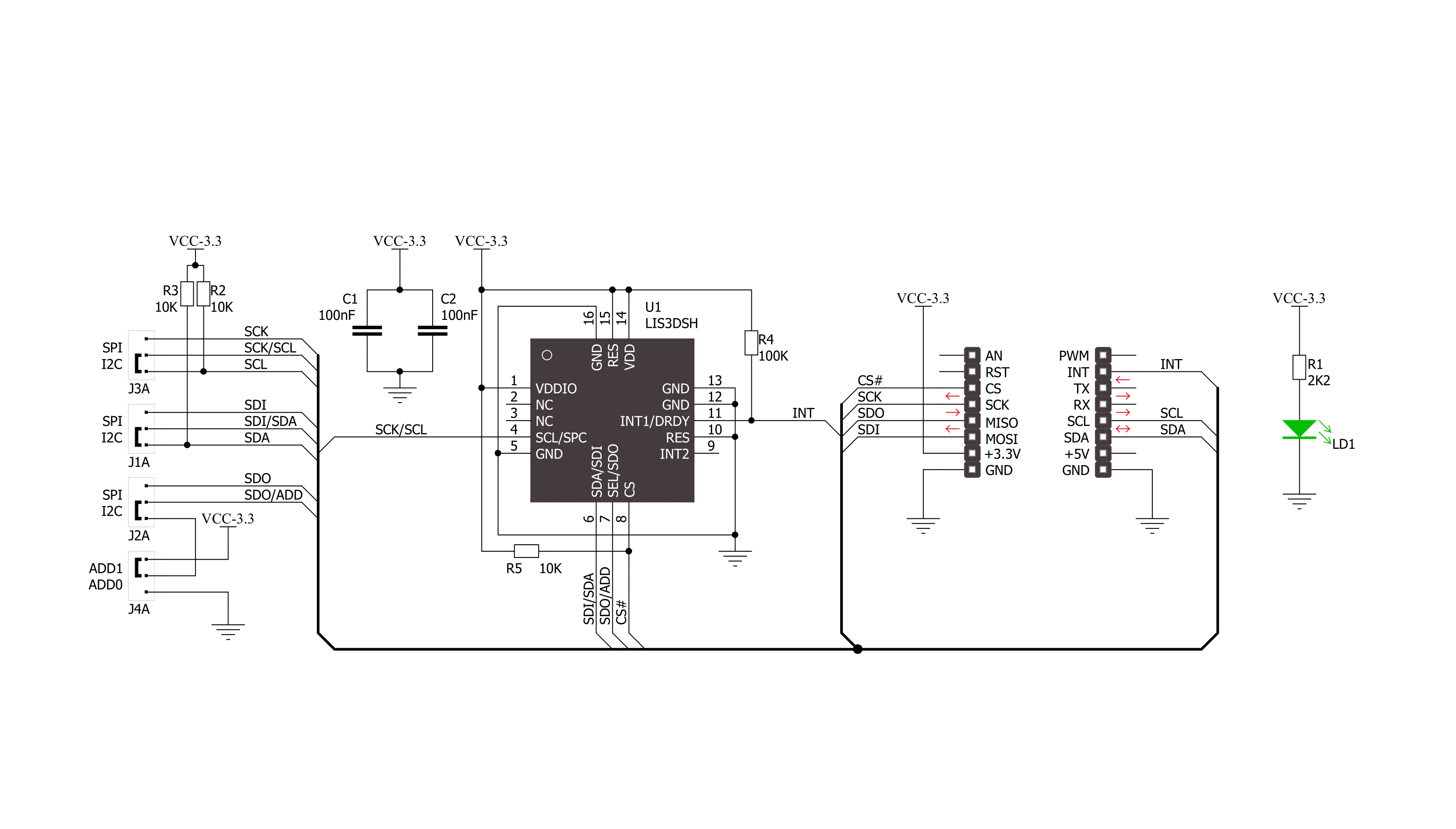
Accel 2 Click is based on the LIS3DSH, a highly reliable digital triaxial acceleration from STMicroelectronics, with an embedded state machine that can be programmed to implement autonomous applications. The LIS3DSH is highly configurable with a programmable acceleration range of ±2g, ±4g, ±6g, ±8g, or ±16g, capable of measuring accelerations with selectable output data rates from 3.125Hz up to 1.6kHz. It supports high-performance and low-power operating modes, allowing maximum flexibility to meet the resolution and power needs of various motion control use cases. The LIS3DSH has an integrated first-in, first-out (FIFO) buffer for each of the three output channels, X, Y, and Z, allowing the user to store data to limit intervention by the host
processor. FIFO allows consistent power saving for the system since the host MCU does not need to poll data continuously from the sensor. Still, it can wake up only when needed and burst the essential data from the FIFO. Accel 2 Click allows the use of both I2C and SPI interfaces with a maximum frequency of 400kHz for I2C and 10MHz for SPI communication. The selection can be made by positioning SMD jumpers labeled SEL COMM in an appropriate position. Note that all the jumpers' positions must be on the same side, or the Click board™ may become unresponsive. While the I2C interface is selected, the LIS3DSH allows choosing the least significant bit (LSB) of its I2C slave address using the SMD jumper labeled I2C ADD. In addition to communication pins, this
board also possesses an additional interrupt pin, routed to the INT pin on the mikroBUS™ socket, indicating when a new set of measured acceleration data is available, simplifying data synchronization in the digital system that uses the device. Also, the user-defined programs can distinguish movement patterns like shake and double shake, face up and face down, turn and double turn, and then activate an interrupt upon execution. This Click board™ can be operated only with a 3.3V logic voltage level. The board must perform appropriate logic voltage level conversion before using MCUs with different logic levels. Also, it comes equipped with a library containing functions and an example code that can be used as a reference for further development.

Features overview
Development board
EasyAVR v7 is the seventh generation of AVR development boards specially designed for the needs of rapid development of embedded applications. It supports a wide range of 16-bit AVR microcontrollers from Microchip and has a broad set of unique functions, such as a powerful onboard mikroProg programmer and In-Circuit debugger over USB. The development board is well organized and designed so that the end-user has all the necessary elements in one place, such as switches, buttons, indicators, connectors, and others. With four different connectors for each port, EasyAVR v7 allows you to connect accessory boards, sensors, and custom electronics more
efficiently than ever. Each part of the EasyAVR v7 development board contains the components necessary for the most efficient operation of the same board. An integrated mikroProg, a fast USB 2.0 programmer with mikroICD hardware In-Circuit Debugger, offers many valuable programming/debugging options and seamless integration with the Mikroe software environment. Besides it also includes a clean and regulated power supply block for the development board. It can use a wide range of external power sources, including an external 12V power supply, 7-12V AC or 9-15V DC via DC connector/screw terminals, and a power source via the USB Type-B (USB-B)
connector. Communication options such as USB-UART and RS-232 are also included, alongside the well-established mikroBUS™ standard, three display options (7-segment, graphical, and character-based LCD), and several different DIP sockets which cover a wide range of 16-bit AVR MCUs. EasyAVR v7 is an integral part of the Mikroe ecosystem for rapid development. Natively supported by Mikroe software tools, it covers many aspects of prototyping and development thanks to a considerable number of different Click boards™ (over a thousand boards), the number of which is growing every day.

Microcontroller Overview
MCU Card / MCU

Architecture
AVR
MCU Memory (KB)
64
Silicon Vendor
Microchip
Pin count
40
RAM (Bytes)
4096
Used MCU Pins
mikroBUS™ mapper
Take a closer look
Click board™ Schematic
Step by step
Project assembly

Start by selecting your development board and Click board™. Begin with the EasyAVR v7 as your development board.


Track your results in real time
Application Output
1. Application Output - In Debug mode, the 'Application Output' window enables real-time data monitoring, offering direct insight into execution results. Ensure proper data display by configuring the environment correctly using the provided tutorial.

2. UART Terminal - Use the UART Terminal to monitor data transmission via a USB to UART converter, allowing direct communication between the Click board™ and your development system. Configure the baud rate and other serial settings according to your project's requirements to ensure proper functionality. For step-by-step setup instructions, refer to the provided tutorial.

3. Plot Output - The Plot feature offers a powerful way to visualize real-time sensor data, enabling trend analysis, debugging, and comparison of multiple data points. To set it up correctly, follow the provided tutorial, which includes a step-by-step example of using the Plot feature to display Click board™ readings. To use the Plot feature in your code, use the function: plot(*insert_graph_name*, variable_name);. This is a general format, and it is up to the user to replace 'insert_graph_name' with the actual graph name and 'variable_name' with the parameter to be displayed.

Software Support
Library Description
This library contains API for Accel2 Click driver.
Key functions:
accel2_check_id- Check Accel 2 IDaccel2_read_xaxis- Function read X axisaccel2_read_yaxis- Function read Y axis
Open Source
Code example
The complete application code and a ready-to-use project are available through the NECTO Studio Package Manager for direct installation in the NECTO Studio. The application code can also be found on the MIKROE GitHub account.
/*!
 * \file
 * \brief Accel2 Click example
 *
 * # Description
 * This application is three-axis accelerometer which embeds.
 *
 * The demo application is composed of two sections :
 *
 * ## Application Init
 * Initialization device. Check sensor ID and initialize Accel 2 Click.
 *
 * ## Application Task
 * This is a example which demonstrates the use of Accel 2 Click board.
   Measured coordinates (X,Y,Z) are being sent to the UART where you can track their changes.
 *
 * \author MikroE Team
 *
 */
// ------------------------------------------------------------------- INCLUDES

#include "board.h"
#include "log.h"
#include "accel2.h"

// ------------------------------------------------------------------ VARIABLES

static accel2_t accel2;
static log_t logger;

// ------------------------------------------------------ APPLICATION FUNCTIONS

void application_init ( void )
{
    log_cfg_t log_cfg;
    accel2_cfg_t cfg;
	uint8_t cfg_byte = 0;

    /**
     * Logger initialization.
     * Default baud rate: 115200
     * Default log level: LOG_LEVEL_DEBUG
     * @note If USB_UART_RX and USB_UART_TX
     * are defined as HAL_PIN_NC, you will
     * need to define them manually for log to work.
     * See @b LOG_MAP_USB_UART macro definition for detailed explanation.
     */
    LOG_MAP_USB_UART( log_cfg );
    log_init( &logger, &log_cfg );
    log_info( &logger, "---- Application Init ----" );

    //  Click initialization.

    accel2_cfg_setup( &cfg );
    ACCEL2_MAP_MIKROBUS( cfg, MIKROBUS_1 );
    accel2_init( &accel2, &cfg );
	Delay_ms ( 100 );
	accel2_setting( &accel2 );
	Delay_ms ( 100 );
	cfg_byte = accel2_check_id( &accel2 );
	if ( cfg_byte )
	{
		log_info( &logger, "---- ID ERROR ----" );
		for ( ; ; );
	}
	else
	{
		log_info( &logger, "---- ID OK ----" );
	}
}

void application_task ( void )
{
    int16_t value_x;
    int16_t value_y;
    int16_t value_z;

    value_x = accel2_read_xaxis( &accel2 );
    value_y = accel2_read_yaxis( &accel2 );
    value_z = accel2_read_zaxis( &accel2 );

    log_printf( &logger, "Axis X: %d\r\n", value_x );
    log_printf( &logger, "Axis Y: %d\r\n", value_y );
    log_printf( &logger, "Axis Z: %d\r\n", value_z );
    log_printf( &logger, "-------------------------------\r\n" );

    Delay_ms ( 500 );
}

int main ( void )
{
    /* Do not remove this line or clock might not be set correctly. */
    #ifdef PREINIT_SUPPORTED
    preinit();
    #endif

    application_init( );

    for ( ; ; )
    {
        application_task( );
    }

    return 0;
}

// ------------------------------------------------------------------------ END
Additional Support
Resources
Category:Motion


