Unleash the power of LEDs with MCP1664 and ATmega32
Illuminate and enchant

Published Nov 01, 2023
Click board™
MCP1664 Click
Dev. board
EasyAVR v7
Compiler
NECTO Studio
MCU
ATmega32
Illuminate every space confidently using our white LED driver solution, ensuring vibrant, energy-efficient lighting that captivates and enhances any environment
A
A
Hardware Overview
How does it work?
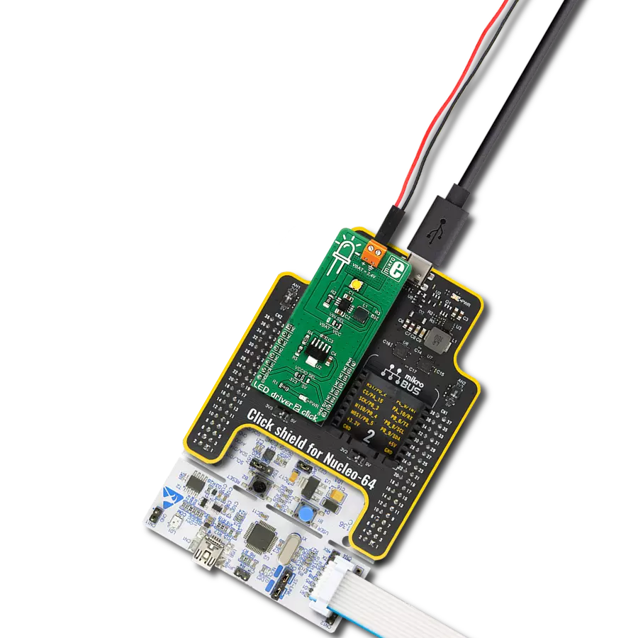
MCP1664 Click is based on four high-power white LEDs. It carries the MCP1664, a high-voltage step-up LED driver from Microchip. MCP1664 click is designed to run on either a 3.3V or 5V power supply. It communicates with the target board microcontroller over the PWM pin on the mikroBUS™ line. The click has a power and PWM input to set the light intensity at the desired level. The MCP1664 is a compact, space-efficient, fixed-frequency, non-synchronous step-up converter
optimized to drive multiple strings of LEDs with constant current powered from two and three-cell alkaline or NiMH/NiCd as well as from one-cell Li-Ion or Li-Polymer batteries. The MCP1664 features open load protection (OLP), which turns off the operation when the LED string is accidentally disconnected or the feedback pin is short-circuited to GND. While in Shutdown mode (EN = GND), the device stops switching and consumes 40 nA, typical of the input current. This Click
board™ can operate with either 3.3V or 5V logic voltage levels selected via the VCC SEL jumper. This way, both 3.3V and 5V capable MCUs can use the communication lines properly. Also, this Click board™ comes equipped with a library containing easy-to-use functions and an example code that can be used as a reference for further development.


Features overview
Development board
EasyAVR v7 is the seventh generation of AVR development boards specially designed for the needs of rapid development of embedded applications. It supports a wide range of 16-bit AVR microcontrollers from Microchip and has a broad set of unique functions, such as a powerful onboard mikroProg programmer and In-Circuit debugger over USB. The development board is well organized and designed so that the end-user has all the necessary elements in one place, such as switches, buttons, indicators, connectors, and others. With four different connectors for each port, EasyAVR v7 allows you to connect accessory boards, sensors, and custom electronics more
efficiently than ever. Each part of the EasyAVR v7 development board contains the components necessary for the most efficient operation of the same board. An integrated mikroProg, a fast USB 2.0 programmer with mikroICD hardware In-Circuit Debugger, offers many valuable programming/debugging options and seamless integration with the Mikroe software environment. Besides it also includes a clean and regulated power supply block for the development board. It can use a wide range of external power sources, including an external 12V power supply, 7-12V AC or 9-15V DC via DC connector/screw terminals, and a power source via the USB Type-B (USB-B)
connector. Communication options such as USB-UART and RS-232 are also included, alongside the well-established mikroBUS™ standard, three display options (7-segment, graphical, and character-based LCD), and several different DIP sockets which cover a wide range of 16-bit AVR MCUs. EasyAVR v7 is an integral part of the Mikroe ecosystem for rapid development. Natively supported by Mikroe software tools, it covers many aspects of prototyping and development thanks to a considerable number of different Click boards™ (over a thousand boards), the number of which is growing every day.

Microcontroller Overview
MCU Card / MCU

Architecture
AVR
MCU Memory (KB)
32
Silicon Vendor
Microchip
Pin count
40
RAM (Bytes)
2048
Used MCU Pins
mikroBUS™ mapper
Take a closer look
Click board™ Schematic

Step by step
Project assembly

Start by selecting your development board and Click board™. Begin with the EasyAVR v7 as your development board.


Track your results in real time
Application Output
1. Application Output - In Debug mode, the 'Application Output' window enables real-time data monitoring, offering direct insight into execution results. Ensure proper data display by configuring the environment correctly using the provided tutorial.

2. UART Terminal - Use the UART Terminal to monitor data transmission via a USB to UART converter, allowing direct communication between the Click board™ and your development system. Configure the baud rate and other serial settings according to your project's requirements to ensure proper functionality. For step-by-step setup instructions, refer to the provided tutorial.

3. Plot Output - The Plot feature offers a powerful way to visualize real-time sensor data, enabling trend analysis, debugging, and comparison of multiple data points. To set it up correctly, follow the provided tutorial, which includes a step-by-step example of using the Plot feature to display Click board™ readings. To use the Plot feature in your code, use the function: plot(*insert_graph_name*, variable_name);. This is a general format, and it is up to the user to replace 'insert_graph_name' with the actual graph name and 'variable_name' with the parameter to be displayed.

Software Support
Library Description
This library contains API for MCP1664 Click driver.
Key functions:
mcp1664_pwm_start- Start PWM modulemcp1664_pwm_stop- Stop PWM module
Open Source
Code example
The complete application code and a ready-to-use project are available through the NECTO Studio Package Manager for direct installation in the NECTO Studio. The application code can also be found on the MIKROE GitHub account.
/*!
 * \file
 * \brief Mcp1664 Click example
 *
 * # Description
 * This application turn on and turn off white LEDs.
 *
 * The demo application is composed of two sections :
 *
 * ## Application Init
 * Enables GPIO and PWM, sets the frequency and duty cycle and enables PWM.
 *
 * ## Application Task
 * This is a example which demonstrates the use of MCP1664 Click board.
 * It shows how to enable the device and gradualy increase the duty cycle.
 *
 * \author MikroE Team
 *
 */
// ------------------------------------------------------------------- INCLUDES

#include "board.h"
#include "log.h"
#include "mcp1664.h"

// ------------------------------------------------------------------ VARIABLES

static mcp1664_t mcp1664;
static log_t logger;

static float duty_cycle = 0.5;

// ------------------------------------------------------ APPLICATION FUNCTIONS

void application_init ( void )
{
    log_cfg_t log_cfg;
    mcp1664_cfg_t cfg;

    /**
     * Logger initialization.
     * Default baud rate: 115200
     * Default log level: LOG_LEVEL_DEBUG
     * @note If USB_UART_RX and USB_UART_TX
     * are defined as HAL_PIN_NC, you will
     * need to define them manually for log to work.
     * See @b LOG_MAP_USB_UART macro definition for detailed explanation.
     */
    LOG_MAP_USB_UART( log_cfg );
    log_init( &logger, &log_cfg );
    log_info( &logger, "---- Application Init ----" );

    //  Click initialization.

    mcp1664_cfg_setup( &cfg );
    MCP1664_MAP_MIKROBUS( cfg, MIKROBUS_1 );
    mcp1664_init( &mcp1664, &cfg );

    mcp1664_set_duty_cycle( &mcp1664, duty_cycle );
    mcp1664_pwm_start( &mcp1664 );
    Delay_ms ( 1000 );
    log_printf( &logger, "------------------ \r\n" );
    log_printf( &logger, "  MCP1664  Click   \r\n" );
    log_printf( &logger, "------------------ \r\n" );
    Delay_ms ( 100 );
}

void application_task ( void )
{
    //  Task implementation.

    if ( duty_cycle > 1 )
    {
        duty_cycle = 0.1;
    }

    mcp1664_set_duty_cycle ( &mcp1664, duty_cycle );
    duty_cycle += 0.1;
    Delay_100ms();

    log_printf( &logger,  "  Duty cycle is : %d  \r\n", duty_cycle );
}

int main ( void )
{
    /* Do not remove this line or clock might not be set correctly. */
    #ifdef PREINIT_SUPPORTED
    preinit();
    #endif

    application_init( );

    for ( ; ; )
    {
        application_task( );
    }

    return 0;
}


// ------------------------------------------------------------------------ END