Experience the language of colors like never before with OPT4048 and ATmega324P
Capture the spectrum of possibilities!

Published Nov 11, 2023
Click board™
Color 17 Click
Dev. board
EasyAVR v7
Compiler
NECTO Studio
MCU
ATmega324P
Unlock a world of precision with our color sensing solution, empowering you to capture and utilize the full spectrum of colors for unparalleled applications.
A
A
Hardware Overview
How does it work?
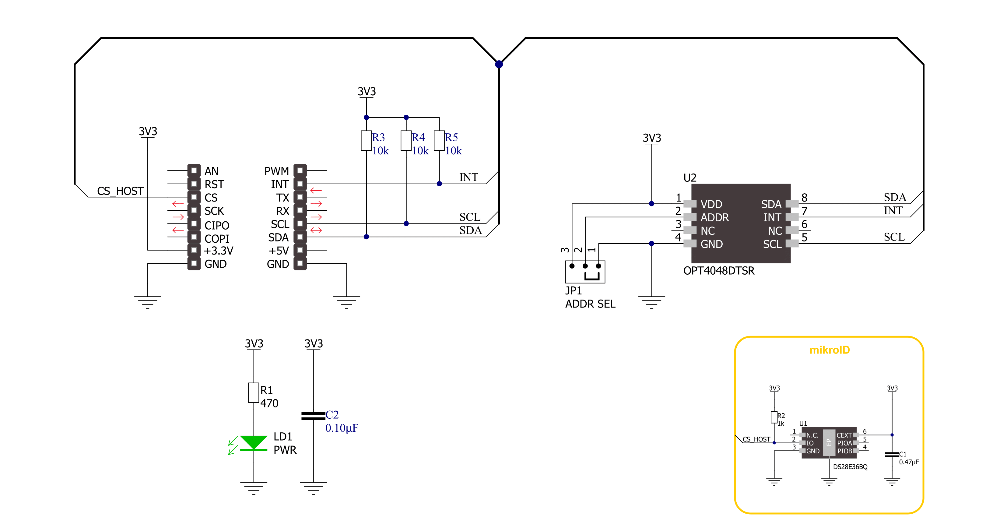
Color 17 Click is based on the OPT4048, a high-speed precision tristimulus XYZ color sensor from Texas Instruments, designed to mimic the human eye’s normal vision. The human eye has spectral sensitivity in a range of short, middle, and long wavelengths but in a correlation with a range of brightness. The CIE XYZ color space represents all color sensations visible to an average human eye, where the X is a mix of the three CIE RGB curves, the Y is the illuminance, and the Z is a quasi-equal to blue, according to the CIE 1931 model. The CIE XYZ is fixed color space, and one must note that there is a difference between the objects that emit light (and color) and objects that reflect light (and color). To put it more clearly, the monitor you look at and the wall behind it. The OPT4048 has three channels closely matching the CIE tristimulus spectra and a fourth with a wide-band spectral response. Measures from these channels give us the characteristics of the lighting environment, such as the light intensity, color, LUV coordinates, and correlated color temperature. While closely mimicking the human eye, the OPT4084
rejects the wavelengths from their peaks, especially the NIR region (infrared) that the human eye does not see, which is a crucial part of this sensor. To achieve excellent filter performance even at higher angles of light incidence, the OPT4084 uses advanced filter technology, high-resolution color measurements, and built-in automatic full-scale light range selection logic. By default, the OPT4048 is configured to operate in an automatic full-scale range detection mode that always selects the best full-scale range setting for the given lighting conditions. There are seven full-scale range settings, one of which can also be selected manually. Setting the device to operate in automatic full-scale range detection mode frees the user from having to program their software for potential iterative cycles of measurement and readjustment of the full-scale range until good for any given measurement. It also shows excellent linearity over the entire 26-bit dynamic range of measurement from 2.15mlux up to 144klux, with a highly linear response within each range. The Color 17 Click uses an I2C 2-Wire interface
supporting a Fast mode of up to 400kHz, and I2C burst mode to communicate with the host MCU. The I2C address can be selected via the ADDR SEL jumper with 0 selected by default. The sensor has several modes of operation: Power-Down mode, Continuous mode as a normal mode of operation, and a one-shot mode in which the sensor can be triggered to work depending on the user setup. One of the triggers can be the interrupt functionality, where the INT pin is used for hardware-synchronized triggers and interrupts. The OPT4084 features a threshold detection logic that allows the MCU to sleep or do other things while the sensor watches when an appropriate interrupt event occurs. This Click board™ can be operated only with a 3.3V logic voltage level. The board must perform appropriate logic voltage level conversion before using MCUs with different logic levels. Also, it comes equipped with a library containing functions and an example code that can be used as a reference for further development.

Features overview
Development board
EasyAVR v7 is the seventh generation of AVR development boards specially designed for the needs of rapid development of embedded applications. It supports a wide range of 16-bit AVR microcontrollers from Microchip and has a broad set of unique functions, such as a powerful onboard mikroProg programmer and In-Circuit debugger over USB. The development board is well organized and designed so that the end-user has all the necessary elements in one place, such as switches, buttons, indicators, connectors, and others. With four different connectors for each port, EasyAVR v7 allows you to connect accessory boards, sensors, and custom electronics more
efficiently than ever. Each part of the EasyAVR v7 development board contains the components necessary for the most efficient operation of the same board. An integrated mikroProg, a fast USB 2.0 programmer with mikroICD hardware In-Circuit Debugger, offers many valuable programming/debugging options and seamless integration with the Mikroe software environment. Besides it also includes a clean and regulated power supply block for the development board. It can use a wide range of external power sources, including an external 12V power supply, 7-12V AC or 9-15V DC via DC connector/screw terminals, and a power source via the USB Type-B (USB-B)
connector. Communication options such as USB-UART and RS-232 are also included, alongside the well-established mikroBUS™ standard, three display options (7-segment, graphical, and character-based LCD), and several different DIP sockets which cover a wide range of 16-bit AVR MCUs. EasyAVR v7 is an integral part of the Mikroe ecosystem for rapid development. Natively supported by Mikroe software tools, it covers many aspects of prototyping and development thanks to a considerable number of different Click boards™ (over a thousand boards), the number of which is growing every day.

Microcontroller Overview
MCU Card / MCU

Architecture
AVR
MCU Memory (KB)
32
Silicon Vendor
Microchip
Pin count
40
RAM (Bytes)
2048
Used MCU Pins
mikroBUS™ mapper
Take a closer look
Click board™ Schematic
Step by step
Project assembly

Start by selecting your development board and Click board™. Begin with the EasyAVR v7 as your development board.


Track your results in real time
Application Output
1. Application Output - In Debug mode, the 'Application Output' window enables real-time data monitoring, offering direct insight into execution results. Ensure proper data display by configuring the environment correctly using the provided tutorial.

2. UART Terminal - Use the UART Terminal to monitor data transmission via a USB to UART converter, allowing direct communication between the Click board™ and your development system. Configure the baud rate and other serial settings according to your project's requirements to ensure proper functionality. For step-by-step setup instructions, refer to the provided tutorial.

3. Plot Output - The Plot feature offers a powerful way to visualize real-time sensor data, enabling trend analysis, debugging, and comparison of multiple data points. To set it up correctly, follow the provided tutorial, which includes a step-by-step example of using the Plot feature to display Click board™ readings. To use the Plot feature in your code, use the function: plot(*insert_graph_name*, variable_name);. This is a general format, and it is up to the user to replace 'insert_graph_name' with the actual graph name and 'variable_name' with the parameter to be displayed.

Software Support
Library Description
This library contains API for Color 17 Click driver.
Key functions:
color17_get_cct- Color 17 gets correlated color temperature data function.color17_get_measurement- Color 17 gets light and color measurement data function.color17_set_config- Color 17 set the configuration function.
Open Source
Code example
The complete application code and a ready-to-use project are available through the NECTO Studio Package Manager for direct installation in the NECTO Studio. The application code can also be found on the MIKROE GitHub account.
/*!
 * @file main.c
 * @brief Color 17 Click example
 *
 * # Description
 * This library contains API for the Color 17 Click driver.
 * This example displays CCT data, Light intensity level
 * and the light color names.
 *
 * The demo application is composed of two sections :
 *
 * ## Application Init
 * Initialization of I2C module and log UART.
 * After driver initialization, default settings turn on the device.
 *
 * ## Application Task
 * This example demonstrates the use of the Color 17 Click board™.
 * Reads and displays the correlated color temperature
 * and Light intensity level.
 * This example also detects and displays the light color names.
 * Results are being sent to the UART Terminal, where you can track their changes.
 *
 * @note
 * Color detection is obtained based on the analysis
 * of calculate the correlated color temperature (CCT) data
 * and the CIE 1931 chromaticity diagram. For more details please refer to the
 * “OPT4048 High Speed High Precision Tristimulus XYZ Color Sensor datasheet”
 * (https://www.ti.com/lit/gpn/OPT4048).

 * @author Nenad Filipovic
 *
 */

#include "board.h"
#include "log.h"
#include "color17.h"

#define COLOR17_LIM_DARK_LUX                10.0
#define COLOR17_CCT_LIM_BLUE_COLOR          7000
#define COLOR17_CCT_LIM_LIGHT_BLUE_COLOR    4000
#define COLOR17_CCT_LIM_GREEN_COLOR         3100
#define COLOR17_CCT_LIM_YELLOW_COLOR        2400
#define COLOR17_CCT_LIM_ORANGE_COLOR        1950
#define COLOR17_CCT_LIM_RED_COLOR           1600

static color17_t color17;
static log_t logger;
static float light_intensity, cct;

/**
 * @brief Color 17 display color function.
 * @details This function displays the light color names.
 * @return Nothing.
 * @note None.
 */
void color17_display_color ( void );

void application_init ( void )
{
    log_cfg_t log_cfg;  /**< Logger config object. */
    color17_cfg_t color17_cfg;  /**< Click config object. */

    /**
     * Logger initialization.
     * Default baud rate: 115200
     * Default log level: LOG_LEVEL_DEBUG
     * @note If USB_UART_RX and USB_UART_TX
     * are defined as HAL_PIN_NC, you will
     * need to define them manually for log to work.
     * See @b LOG_MAP_USB_UART macro definition for detailed explanation.
     */
    LOG_MAP_USB_UART( log_cfg );
    log_init( &logger, &log_cfg );
    log_info( &logger, " Application Init " );

    // Click initialization.
    color17_cfg_setup( &color17_cfg );
    COLOR17_MAP_MIKROBUS( color17_cfg, MIKROBUS_1 );
    if ( I2C_MASTER_ERROR == color17_init( &color17, &color17_cfg ) )
    {
        log_error( &logger, " Communication init." );
        for ( ; ; );
    }

    if ( COLOR17_ERROR == color17_default_cfg ( &color17 ) )
    {
        log_error( &logger, " Default configuration." );
        for ( ; ; );
    }

    log_info( &logger, " Application Task " );
    Delay_ms ( 100 );
}

void application_task ( void )
{
    if ( COLOR17_OK == color17_get_cct( &color17, &cct, &light_intensity ) )
    {
        log_printf( &logger, " CCT: %.2f\r\n", cct );
        log_printf( &logger, " LIL: %.2f\r\n", light_intensity );
        log_printf( &logger, " - - - - - - -  - - - - \r\n" );
        color17_display_color( );
    }
    log_printf( &logger, " ----------------------\r\n" );
    Delay_ms ( 1000 );
}

int main ( void )
{
    /* Do not remove this line or clock might not be set correctly. */
    #ifdef PREINIT_SUPPORTED
    preinit();
    #endif

    application_init( );

    for ( ; ; )
    {
        application_task( );
    }

    return 0;
}

void color17_display_color ( void )
{
    if ( light_intensity < COLOR17_LIM_DARK_LUX )
    {
        log_printf( &logger, " Color DARK\r\n", cct );
    }
    else if ( cct > COLOR17_CCT_LIM_BLUE_COLOR  )
    {
        log_printf( &logger, " Color BLUE\r\n", cct );
    }
    else if ( cct > COLOR17_CCT_LIM_LIGHT_BLUE_COLOR  )
    {
        log_printf( &logger, " Color LIGHT BLUE\r\n", cct );
    }
    else if ( cct > COLOR17_CCT_LIM_GREEN_COLOR )
    {
        log_printf( &logger, " Color GREEN\r\n", cct );
    }
    else if ( cct > COLOR17_CCT_LIM_YELLOW_COLOR )
    {
        log_printf( &logger, " Color YELLOW\r\n", cct );
    }
    else if ( cct > COLOR17_CCT_LIM_ORANGE_COLOR )
    {
        log_printf( &logger, " Color ORANGE\r\n", cct );
    }
    else if ( cct > COLOR17_CCT_LIM_RED_COLOR )
    {
        log_printf( &logger, " Color RED\r\n", cct );
    }
    else
    {
        log_printf( &logger, " Color BLUE\r\n", cct );
    }
}

// ------------------------------------------------------------------------ END


