Ensure reliable and stable LED performance with PCA9957 and ATmega644P
Empowering LEDs for a brighter tomorrow

Published Sep 05, 2023
Click board™
LED Driver 8 Click
Dev. board
EasyAVR v7
Compiler
NECTO Studio
MCU
ATmega644P
Our LED driver is engineered to simplify the integration of LED functionality into your circuit designs, reducing development time and costs
A
A
Hardware Overview
How does it work?
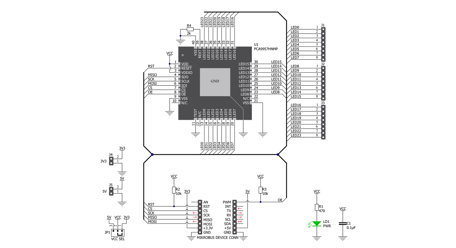
LED Driver 8 Click is based on the PCA9957, a daisy-chain SPI-compatible 4-wire serial bus controlled 24-channel constant current LED driver optimized for dimming and blinking 32 mA RGBA LEDs from NXP Semiconductors. The PCA9957 has 24 internal 8-bit DACs with an operating frequency of 31.25 kHz and a duty cycle from 0% to 100% used to adjust brightness levels for each LED current source. Each LED output is programmable and can be turned off, on (with no PWM control), set at its individual PWM controller value, or both individual and group PWM controller values. Its output peak current is adjustable with an 8-bit linear DAC from 125 μA to 31.875 mA because of the R4 resistor of 2kΩ connected to the REXT pin. Gradation control for all current sources is achieved through a serial interface and
allows the user to ramp current automatically without help from the MCU. It has two operation modes for each group: Single-Shot Mode (output pattern once) and Continuous Mode (output pattern repeat). Each channel can be set to either Gradation Mode or Normal Mode and assigned to any of the six gradation control groups. These groups have four independent registers to control ramp-up and ramp-down rate, step time, hold ON/OFF time, and final hold ON output current. The LED Driver 8 Click communicates with MCU through a daisy-chain SPI-compatible 4-wire serial interface with a clock frequency of up to 10 MHz. The input labeled as OE routed to the PWM pin on the mikroBUS™ blinks all the LED outputs and can be used to externally PWM the outputs, which is useful when multiple devices need to be
dimmed or blinked together without software control. The PCA9957 also has a short load and overtemperature detection circuitry, a thermal shutdown feature that protects the device when the internal junction temperature exceeds the factory-defined limit, and a Reset function routed to the RST pin on the mikroBUS™ which is activated by sending an active low input on this pin with a minimum pulse width of 2.5μs. This Click board™ can operate with either 3.3V or 5V logic voltage levels selected via the VCC SEL jumper. This way, both 3.3V and 5V capable MCUs can use the communication lines properly. Also, this Click board™ comes equipped with a library containing easy-to-use functions and an example code that can be used as a reference for further development.

Features overview
Development board
EasyAVR v7 is the seventh generation of AVR development boards specially designed for the needs of rapid development of embedded applications. It supports a wide range of 16-bit AVR microcontrollers from Microchip and has a broad set of unique functions, such as a powerful onboard mikroProg programmer and In-Circuit debugger over USB. The development board is well organized and designed so that the end-user has all the necessary elements in one place, such as switches, buttons, indicators, connectors, and others. With four different connectors for each port, EasyAVR v7 allows you to connect accessory boards, sensors, and custom electronics more
efficiently than ever. Each part of the EasyAVR v7 development board contains the components necessary for the most efficient operation of the same board. An integrated mikroProg, a fast USB 2.0 programmer with mikroICD hardware In-Circuit Debugger, offers many valuable programming/debugging options and seamless integration with the Mikroe software environment. Besides it also includes a clean and regulated power supply block for the development board. It can use a wide range of external power sources, including an external 12V power supply, 7-12V AC or 9-15V DC via DC connector/screw terminals, and a power source via the USB Type-B (USB-B)
connector. Communication options such as USB-UART and RS-232 are also included, alongside the well-established mikroBUS™ standard, three display options (7-segment, graphical, and character-based LCD), and several different DIP sockets which cover a wide range of 16-bit AVR MCUs. EasyAVR v7 is an integral part of the Mikroe ecosystem for rapid development. Natively supported by Mikroe software tools, it covers many aspects of prototyping and development thanks to a considerable number of different Click boards™ (over a thousand boards), the number of which is growing every day.

Microcontroller Overview
MCU Card / MCU

Architecture
AVR
MCU Memory (KB)
64
Silicon Vendor
Microchip
Pin count
40
RAM (Bytes)
4096
Used MCU Pins
mikroBUS™ mapper
Take a closer look
Click board™ Schematic
Step by step
Project assembly

Start by selecting your development board and Click board™. Begin with the EasyAVR v7 as your development board.


Track your results in real time
Application Output
1. Application Output - In Debug mode, the 'Application Output' window enables real-time data monitoring, offering direct insight into execution results. Ensure proper data display by configuring the environment correctly using the provided tutorial.

2. UART Terminal - Use the UART Terminal to monitor data transmission via a USB to UART converter, allowing direct communication between the Click board™ and your development system. Configure the baud rate and other serial settings according to your project's requirements to ensure proper functionality. For step-by-step setup instructions, refer to the provided tutorial.

3. Plot Output - The Plot feature offers a powerful way to visualize real-time sensor data, enabling trend analysis, debugging, and comparison of multiple data points. To set it up correctly, follow the provided tutorial, which includes a step-by-step example of using the Plot feature to display Click board™ readings. To use the Plot feature in your code, use the function: plot(*insert_graph_name*, variable_name);. This is a general format, and it is up to the user to replace 'insert_graph_name' with the actual graph name and 'variable_name' with the parameter to be displayed.

Software Support
Library Description
This library contains API for LED Driver 8 Click driver.
Key functions:
leddriver8_set_brightness- Function for set brightnessleddriver8_set_output_gain- Function for set output gainleddriver8_set_mode_register- Function for set mode registers
Open Source
Code example
The complete application code and a ready-to-use project are available through the NECTO Studio Package Manager for direct installation in the NECTO Studio. The application code can also be found on the MIKROE GitHub account.
/*!
 * \file
 * \brief LedDriver8 Click example
 *
 * # Description
 * This example demonstrates the use of LED Driver 8 Click board.
 *
 * The demo application is composed of two sections :
 *
 * ## Application Init
 * Initializes the driver and configures the click board.
 *
 * ## Application Task
 * Increases the LEDs brightness then toggles all LEDs with a one-second delay.
 * Each step will be logged on the USB UART where you can track the program flow.
 *
 * \author MikroE Team
 *
 */
// ------------------------------------------------------------------- INCLUDES

#include "board.h"
#include "log.h"
#include "leddriver8.h"

// ------------------------------------------------------------------ VARIABLES

static leddriver8_t leddriver8;
static log_t logger;

// ------------------------------------------------------ APPLICATION FUNCTIONS

void application_init ( void )
{
    log_cfg_t log_cfg;
    leddriver8_cfg_t cfg;

    /**
     * Logger initialization.
     * Default baud rate: 115200
     * Default log level: LOG_LEVEL_DEBUG
     * @note If USB_UART_RX and USB_UART_TX
     * are defined as HAL_PIN_NC, you will
     * need to define them manually for log to work.
     * See @b LOG_MAP_USB_UART macro definition for detailed explanation.
     */
    LOG_MAP_USB_UART( log_cfg );
    log_init( &logger, &log_cfg );
    log_info( &logger, "---- Application Init ----" );

    //  Click initialization.

    leddriver8_cfg_setup( &cfg );
    LEDDRIVER8_MAP_MIKROBUS( cfg, MIKROBUS_1 );
    leddriver8_init( &leddriver8, &cfg );

    leddriver8_reset( &leddriver8 );
    Delay_ms ( 500 );

    leddriver8_output_enable_pin( &leddriver8, LEDDRIVER8_ENABLE_LED_OUTPUTS );
    leddriver8_set_output_gain( &leddriver8, LEDDRIVER8_OUTPUT_GAIN_ALL_LED, LEDDRIVER8_FULL_OUTPUT_CURRENT_GAIN );
    leddriver8_set_mode_register( &leddriver8, LEDDRIVER8_MODE1_NORMAL_MODE, LEDDRIVER8_MODE2_DMBLNK_DIMMING |
                                  LEDDRIVER8_MODE2_CLRERR_ALL | LEDDRIVER8_MODE2_EXP_DISABLE );
    log_info( &logger, "---- Application Task ----" );
    Delay_ms ( 500 );
}

void application_task ( void )
{
    uint16_t cnt;

    log_printf( &logger, "Increasing LEDs brightness...\r\n" );
    log_printf( &logger, "----------------------------\r\n" );
    for ( cnt = LEDDRIVER8_MIN_BRIGHTNESS; cnt <= LEDDRIVER8_MAX_BRIGHTNESS; cnt++ )
    {
        leddriver8_set_brightness( &leddriver8, LEDDRIVER8_BRIGHTNESS_ALL_LED, cnt );
        Delay_ms ( 20 );
    }

    log_printf( &logger, "Toggling all LEDs...\r\n" );
    log_printf( &logger, "----------------------------\r\n" );
    for ( cnt = 0; cnt < 5; cnt++ )
    {
       leddriver8_set_brightness( &leddriver8, LEDDRIVER8_BRIGHTNESS_ALL_LED, LEDDRIVER8_MAX_BRIGHTNESS );
       Delay_ms ( 1000 );
       leddriver8_set_brightness( &leddriver8, LEDDRIVER8_BRIGHTNESS_ALL_LED, LEDDRIVER8_MIN_BRIGHTNESS );
       Delay_ms ( 1000 );
    }
}

int main ( void )
{
    /* Do not remove this line or clock might not be set correctly. */
    #ifdef PREINIT_SUPPORTED
    preinit();
    #endif

    application_init( );

    for ( ; ; )
    {
        application_task( );
    }

    return 0;
}

// ------------------------------------------------------------------------ END


