Effectively expand the capabilities of your I2C bus using TCA9546A and ATmega644
Switch and multiplex signals with ease

Published Sep 10, 2023
Click board™
I2C MUX Click
Dev. board
EasyAVR v7
Compiler
NECTO Studio
MCU
ATmega644
Our I2C multiplexer is designed to enhance and simplify your I2C communication by providing seamless control over multiple I2C devices, allowing you to efficiently manage address conflicts and streamline data exchange
A
A
Hardware Overview
How does it work?
I2C MUX Click is based on the TCA9546A, a quad bidirectional translating switch controlled via the I2C bus from texas instruments. The SCL/SDA upstream pair fans out to four downstream pairs, or channels. Any individual SCn/SDn channel or combination of channels can be selected, determined by the contents of the programmable control register. An active-low reset (RESET) input allows the TCA9546A to recover from a situation in which one of the downstream I2C buses is stuck in a low state. Pulling RESET low resets the I2C state machine and causes all the channels to be deselected, as does the internal power-on reset function. The pass gates of the switches are constructed such that the VCC pin can be used to limit the maximum high voltage, which will be passed by the TCA9546A. This allows the use of different bus voltages on each pair, so that 1.8-V, 2.5-V, or 3.3-V parts can communicate with 5-V parts without any additional protection. The slave
devices can be connected to four headers located on the top of the I2C MUX click. The TCA9546A supports Standard-Mode (100 kHz) and Fast-Mode (400 kHz) operation. This way, the bus can be used to manage a single 8-bit control register in which the four least significant bits control the enabling and disabling of the 4 switch channels of I2C data flow. The I2C bus is for two-way two-line communication between different ICs or modules. The two lines are a serial data line (SDA) and a serial clock line (SCL). Both lines must be connected to a positive supply via a pullup resistor when connected to the output stages of a device. Data transfer can be initiated only when the bus is not busy. One data bit is transferred during each clock pulse. The data on the SDA line must remain stable during the high period of the clock pulse, as changes in the data line at this time are interpreted as control signals. Applications of the TCA9546A contains an I2C (or SMBus) master
device and up to four I2C slave devices. The downstream channels are ideally used to resolve the I2C slave address conflicts. For example, if four identical digital temperature sensors are needed in the application, one sensor can be connected at each channel: 0, 1, 2, and 3. When the temperature at a specific location needs to be read, the appropriate channel can be enabled and all other channels switched off, the data can be retrieved, and the I2C master can move on and read the next channel. This Click board™ can operate with either 3.3V or 5V logic voltage levels selected via the VCC SEL jumper. This way, both 3.3V and 5V capable MCUs can use the communication lines properly. Also, this Click board™ comes equipped with a library containing easy-to-use functions and an example code that can be used as a reference for further development.


Features overview
Development board
EasyAVR v7 is the seventh generation of AVR development boards specially designed for the needs of rapid development of embedded applications. It supports a wide range of 16-bit AVR microcontrollers from Microchip and has a broad set of unique functions, such as a powerful onboard mikroProg programmer and In-Circuit debugger over USB. The development board is well organized and designed so that the end-user has all the necessary elements in one place, such as switches, buttons, indicators, connectors, and others. With four different connectors for each port, EasyAVR v7 allows you to connect accessory boards, sensors, and custom electronics more
efficiently than ever. Each part of the EasyAVR v7 development board contains the components necessary for the most efficient operation of the same board. An integrated mikroProg, a fast USB 2.0 programmer with mikroICD hardware In-Circuit Debugger, offers many valuable programming/debugging options and seamless integration with the Mikroe software environment. Besides it also includes a clean and regulated power supply block for the development board. It can use a wide range of external power sources, including an external 12V power supply, 7-12V AC or 9-15V DC via DC connector/screw terminals, and a power source via the USB Type-B (USB-B)
connector. Communication options such as USB-UART and RS-232 are also included, alongside the well-established mikroBUS™ standard, three display options (7-segment, graphical, and character-based LCD), and several different DIP sockets which cover a wide range of 16-bit AVR MCUs. EasyAVR v7 is an integral part of the Mikroe ecosystem for rapid development. Natively supported by Mikroe software tools, it covers many aspects of prototyping and development thanks to a considerable number of different Click boards™ (over a thousand boards), the number of which is growing every day.

Microcontroller Overview
MCU Card / MCU

Architecture
AVR
MCU Memory (KB)
64
Silicon Vendor
Microchip
Pin count
40
RAM (Bytes)
4096
Used MCU Pins
mikroBUS™ mapper
Take a closer look
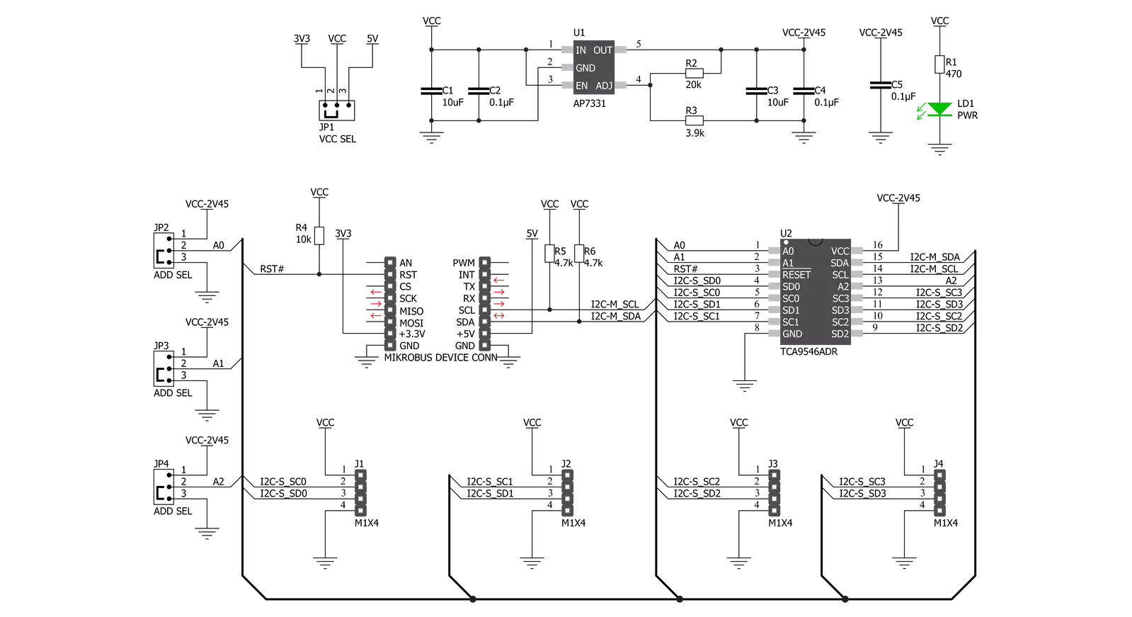
Click board™ Schematic
Step by step
Project assembly

Start by selecting your development board and Click board™. Begin with the EasyAVR v7 as your development board.


Track your results in real time
Application Output
1. Application Output - In Debug mode, the 'Application Output' window enables real-time data monitoring, offering direct insight into execution results. Ensure proper data display by configuring the environment correctly using the provided tutorial.

2. UART Terminal - Use the UART Terminal to monitor data transmission via a USB to UART converter, allowing direct communication between the Click board™ and your development system. Configure the baud rate and other serial settings according to your project's requirements to ensure proper functionality. For step-by-step setup instructions, refer to the provided tutorial.

3. Plot Output - The Plot feature offers a powerful way to visualize real-time sensor data, enabling trend analysis, debugging, and comparison of multiple data points. To set it up correctly, follow the provided tutorial, which includes a step-by-step example of using the Plot feature to display Click board™ readings. To use the Plot feature in your code, use the function: plot(*insert_graph_name*, variable_name);. This is a general format, and it is up to the user to replace 'insert_graph_name' with the actual graph name and 'variable_name' with the parameter to be displayed.

Software Support
Library Description
This library contains API for I2C MUX Click driver.
Key functions:
i2cmux_hw_reset- This function resets I2C MUX 2 click board by clearing the RST pin for 100msi2cmux_set_channel- This function sets channel of the I2C MUX click boardi2cmux_generic_read- This function reads data from the desired register.
Open Source
Code example
The complete application code and a ready-to-use project are available through the NECTO Studio Package Manager for direct installation in the NECTO Studio. The application code can also be found on the MIKROE GitHub account.
/*!
 * \file
 * \brief I2cMux Click example
 *
 * # Description
 * This example demonstrates the use of I2C MUX Click board.
 *
 * The demo application is composed of two sections :
 *
 * ## Application Init
 * Initalizes the driver, preforms hardware reset, then enables channel 0 and
 * makes an initial log.
 *
 * ## Application Task
 * Reads the device ID of a Spectrometer Click (dev ID: 0x24) and displays it
 * on the USB UART each second.
 *
 * \author MikroE Team
 *
 */
// ------------------------------------------------------------------- INCLUDES

#include "board.h"
#include "log.h"
#include "i2cmux.h"

// ------------------------------------------------------------------ VARIABLES

static i2cmux_t i2cmux;
static log_t logger;

// ------------------------------------------------------ APPLICATION FUNCTIONS

void application_init ( void )
{
    log_cfg_t log_cfg;
    i2cmux_cfg_t cfg;

    /**
     * Logger initialization.
     * Default baud rate: 115200
     * Default log level: LOG_LEVEL_DEBUG
     * @note If USB_UART_RX and USB_UART_TX
     * are defined as HAL_PIN_NC, you will
     * need to define them manually for log to work.
     * See @b LOG_MAP_USB_UART macro definition for detailed explanation.
     */
    LOG_MAP_USB_UART( log_cfg );
    log_init( &logger, &log_cfg );
    log_info( &logger, "---- Application Init ----" );

    //  Click initialization.

    i2cmux_cfg_setup( &cfg );
    I2CMUX_MAP_MIKROBUS( cfg, MIKROBUS_1 );
    i2cmux_init( &i2cmux, &cfg );
    Delay_ms ( 100 );
    i2cmux_hw_reset( &i2cmux );
    Delay_ms ( 100 );

    i2cmux_set_channel( &i2cmux, I2CMUX_CMD_SET_CH_0, 0x39 );
    log_printf( &logger, " Please connect a Spectrometer Click to channel 0\r\n" );
    log_printf( &logger, "-------------------------------\r\n" );
    Delay_ms ( 1000 );
    Delay_ms ( 1000 );
}

void application_task ( void )
{
    uint8_t rx_data;

    i2cmux_generic_read( &i2cmux, 0x92, &rx_data, 1 );
    log_printf( &logger, " The Click device ID is:  0x%.2X\r\n", ( uint16_t ) rx_data );
    log_printf( &logger, "-------------------------------\r\n" );
    Delay_ms ( 1000 );
}

int main ( void )
{
    /* Do not remove this line or clock might not be set correctly. */
    #ifdef PREINIT_SUPPORTED
    preinit();
    #endif

    application_init( );

    for ( ; ; )
    {
        application_task( );
    }

    return 0;
}

// ------------------------------------------------------------------------ END


