Maintain the ideal conditions for research and experimentation with G6D-1A-ASI and PIC18F97J60
Your trusted thermometer for every environment

Published Nov 09, 2023
Click board™
Thermostat 2 Click
Dev. board
PICPLC16 v7a
Compiler
NECTO Studio
MCU
PIC18F97J60
Stay ahead of potential health risks with our temperature measurement technology, designed to provide early warnings of temperature fluctuations in critical environments.
A
A
Hardware Overview
How does it work?
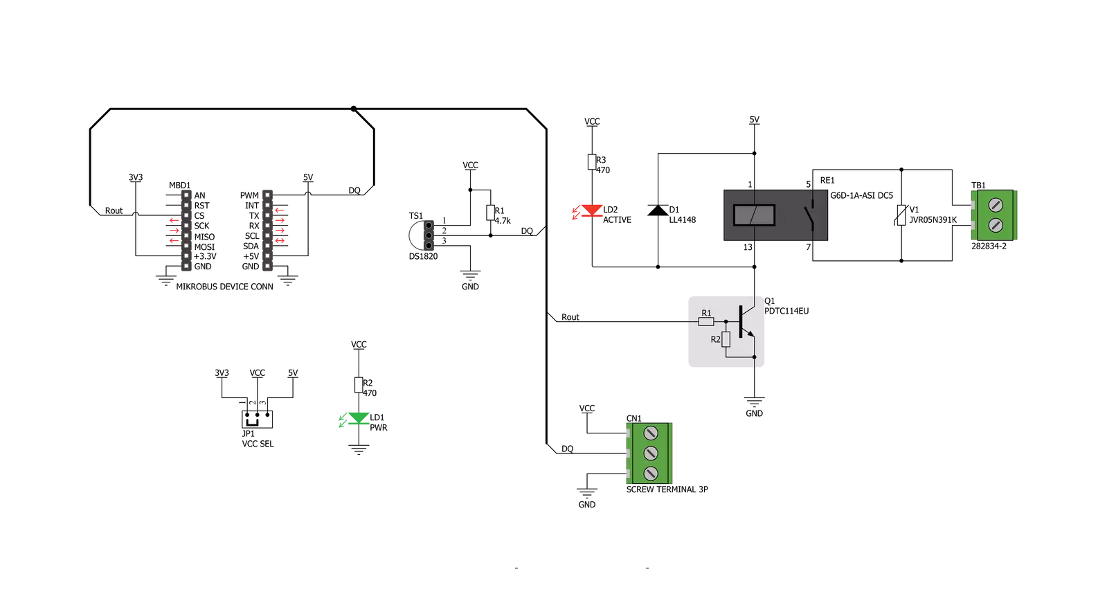
Thermostat 2 Click is designed without the main IC; it allows an externally connected thermal sensor to be used, instead. It can be interfaced with the DS1820 compatible sensor which uses 1-Wire® communication. The Click board™ is equipped with a 3-pin female socket, which can be used to install the DS1820 compatible sensor in TO-92 casing, onboard. There is also a 3-pole screw terminal, that can be used if the sensor needs to be installed on a remote location, i.e. onto a heating component. The screw-terminal shares its lines with the socket. The 1-Wire® communication with the host MCU is performed over the PWM pin of the mikroBUS™. Depending on the temperature information obtained over the 1-Wire® interface, the host MCU can take the necessary action: it can either open or close contacts of the relay. The Click board™ uses the G6D series PCB power relay, from Omron. This quality relay can withstand an amazingly large number of mechanical cycles, with no load connected. However, when there is a significant load connected at its output, micro-electric arcs cause the contacts to wear over time. With the maximum load current of 5A, it can sustain up to 70,000
cycles. Its contacts are made of silver alloy, yielding exceptional ON resistance of only 100mΩ (max). The relay is activated by a magnetic field, generated in a built-in coil on the low-voltage side. The coil is activated by the host MCU. The voltage for the coil activation is 5V, while the current through the coil is 40mA. The MCU is not able to drive the coil directly, therefore an NPN transistor had to be added. Its base is controlled by the host MCU, allowing the coil to drain enough current from the 5V mikroBUS™ power rail. The base of the transistor is routed to the CS pin of the Click board™. The transistor packs two biasing resistors in the same casing, so it can be directly used on the MCU pin, without external biasing resistors. A red color LED, labeled as ACTIVE is used to indicate that the transistor is in an open state and that the current is running through the relay coil. When the current through a coil (or any other inductor) is suddenly changed, the backEMF will be generated, opposing the changes of the current. This can sometimes lead to damage to the control circuit: in this case, the transistor will become inversely polarized. To prevent this from happening, a flyback diode is added
across the coil. During the normal operation, this diode does not conduct any current. However, when the coil is switched OFF, the inverse polarization will cause the current to pass through this diode with minimum resistance. This prevents inverse (flyback) voltage from building up, so the transistor remains safe. Contacts at the output may be connected to a higher voltage and larger current may run through. To prevent high voltage transients in this case, a flyback diode is not a viable option. Therefore, Thermostat 2 click uses a varistor (VDR). This component rapidly drops its resistance as the voltage rises above its rated clamping voltage. The excessive voltage transient will pass through the VDR since it will become a current path with the least resistance. During the normal operation, while the voltage stays below the rated clamping voltage, VDR has a very high resistance, so the current runs through the electrical circuit, instead. The operating voltage of the Click board™ can be selected by the VCC SEL jumper. This jumper allows selecting either 3.3V or 5V from the mikroBUS™. The selected voltage will be applied to the VCC pin of the connected DS1820 sensor.

Features overview
Development board
PICPLC16 v7a is the seventh generation of PIC development boards, providing an environment for experimenting with industrial devices. It comes with an onboard 8-bit PIC microcontroller, the PIC18F97J60 from Microchip, and a broad set of unique functions, such as the first-ever embedded debugger/programmer over USB-C. The development board also consists of 16 opto-inputs and 16 relays for currents up to 16A. It is well organized and designed so that the end-user has all the necessary elements, such as switches, buttons, indicators, and connectors, in one place. With eight connectors for each port, PICPLC16 v7a
allows you to develop PIC-based industrial, home, or office automation applications more efficiently than ever. Each part of the PICPLC16 v7a development board contains the components necessary for the most efficient operation of the same board. In addition to the advanced integrated CODEGRIP programmer/debugger module, which offers many valuable programming/debugging options and seamless integration with the Mikroe software environment, the board also includes a clean and regulated power supply block for the development board. It can use a wide range of external power sources, including an external 12V
power supply, 7-23V AC or 9-32V DC via DC connector/screw terminals, and a power source via the USB Type-C (USB-C) connector. Communication options such as LIN and Ethernet are also included, alongside the well-established mikroBUS™ standard. PICPLC16 v7a is an integral part of the Mikroe ecosystem for rapid industrial development. Natively supported by Mikroe software tools, it covers many aspects of prototyping and development thanks to a considerable number of different Click boards™ (over a thousand boards), the number of which is growing every day.

Microcontroller Overview
MCU Card / MCU
Architecture
PIC
MCU Memory (KB)
128
Silicon Vendor
Microchip
Pin count
100
RAM (Bytes)
3808
Used MCU Pins
mikroBUS™ mapper
Take a closer look
Click board™ Schematic
Step by step
Project assembly

Start by selecting your development board and Click board™. Begin with the PICPLC16 v7a as your development board.


Software Support
Library Description
This library contains API for Thermostat 2 Click driver.
Key functions:
thermostat2_read_temperature- This function reads the temperature value in Celsius.thermostat2_relay_state- This function turns the relay on/off.
Open Source
Code example
The complete application code and a ready-to-use project are available through the NECTO Studio Package Manager for direct installation in the NECTO Studio. The application code can also be found on the MIKROE GitHub account.
/*!
 * @file main.c
 * @brief Thermostat 2 Click Example.
 *
 * # Description
 * This example demonstrates the use of Thermostat 2 Click board by reading
 * and displaying the temperature in Celsius and turning the relay on/off
 * depending on the temperature value.
 * DS1820, DS18S20 and DS18B20 chips can be used in this example.
 *
 * The demo application is composed of two sections :
 *
 * ## Application Init
 * Initializes the driver and performs the Click default configuration.
 *
 * ## Application Task
 * Reads and displays the temperature measured by the Click board on the UART Terminal.
 * If the temperature goes beneath the THERMOSTAT2_TEMPERATURE_LIMIT,
 * the relay will be turned off while otherwise it will be turned on.
 * In both cases an appropriate message will be displayed on the terminal.
 *
 * @author Aleksandra Cvjetićanin
 *
 */

#include "board.h"
#include "log.h"
#include "thermostat2.h"

static thermostat2_t thermostat2;
static log_t logger;

void application_init ( void )
{
    log_cfg_t log_cfg;  /**< Logger config object. */
    thermostat2_cfg_t thermostat2_cfg;  /**< Click config object. */

    /**
     * Logger initialization.
     * Default baud rate: 115200
     * Default log level: LOG_LEVEL_DEBUG
     * @note If USB_UART_RX and USB_UART_TX
     * are defined as HAL_PIN_NC, you will
     * need to define them manually for log to work.
     * See @b LOG_MAP_USB_UART macro definition for detailed explanation.
     */
    LOG_MAP_USB_UART( log_cfg );
    log_init( &logger, &log_cfg );
    log_info( &logger, " Application Init " );

    // Click initialization.
    thermostat2_cfg_setup( &thermostat2_cfg );
    THERMOSTAT2_MAP_MIKROBUS( thermostat2_cfg, MIKROBUS_1 );
    if ( ONE_WIRE_ERROR == thermostat2_init( &thermostat2, &thermostat2_cfg ) )
    {
        log_error( &logger, " Communication init." );
        for ( ; ; );
    }

    if ( THERMOSTAT2_ERROR == thermostat2_default_cfg ( &thermostat2 ) )
    {
        log_error( &logger, " Default config." );
        for ( ; ; );
    }

    log_info( &logger, " Application Task " );
}

void application_task ( void )
{
    static uint8_t relay_state = 0xFF;
    float temperature;

    if ( THERMOSTAT2_OK == thermostat2_read_temperature ( &thermostat2, &temperature ) )
    {
        log_printf( &logger, " Temperature: %.2f C\r\n\n ", temperature );
    }

    if ( temperature < THERMOSTAT2_TEMPERATURE_LIMIT )
    {
        if ( relay_state != THERMOSTAT2_RELAY_ON )
        {
            log_info( &logger, " Relay is ON.\r\n " );
            thermostat2_relay_state ( &thermostat2, THERMOSTAT2_RELAY_ON );
            relay_state = THERMOSTAT2_RELAY_ON;
        }
    }
    else
    {
        if ( relay_state != THERMOSTAT2_RELAY_OFF )
        {
            log_info( &logger, " Relay is OFF.\r\n" );
            thermostat2_relay_state ( &thermostat2, THERMOSTAT2_RELAY_OFF );
            relay_state = THERMOSTAT2_RELAY_OFF;
        }
    }
}

int main ( void )
{
    /* Do not remove this line or clock might not be set correctly. */
    #ifdef PREINIT_SUPPORTED
    preinit();
    #endif

    application_init( );

    for ( ; ; )
    {
        application_task( );
    }

    return 0;
}

// ------------------------------------------------------------------------ END
Additional Support
Resources
Category:Temperature & humidity


