Take control of your data like never before using FT232 and PIC32MZ1024EFH064
Plug, play, and communicate with ease

Published Nov 02, 2023
Click board™
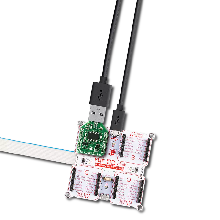
USB UART Click
Dev. board
PIC32MZ clicker
Compiler
NECTO Studio
MCU
PIC32MZ1024EFH064
With our user-friendly USB to UART solution, connecting and communicating with your devices has never been simpler - just plug it in, play with the data, and enjoy seamless communication
A
A
Hardware Overview
How does it work?
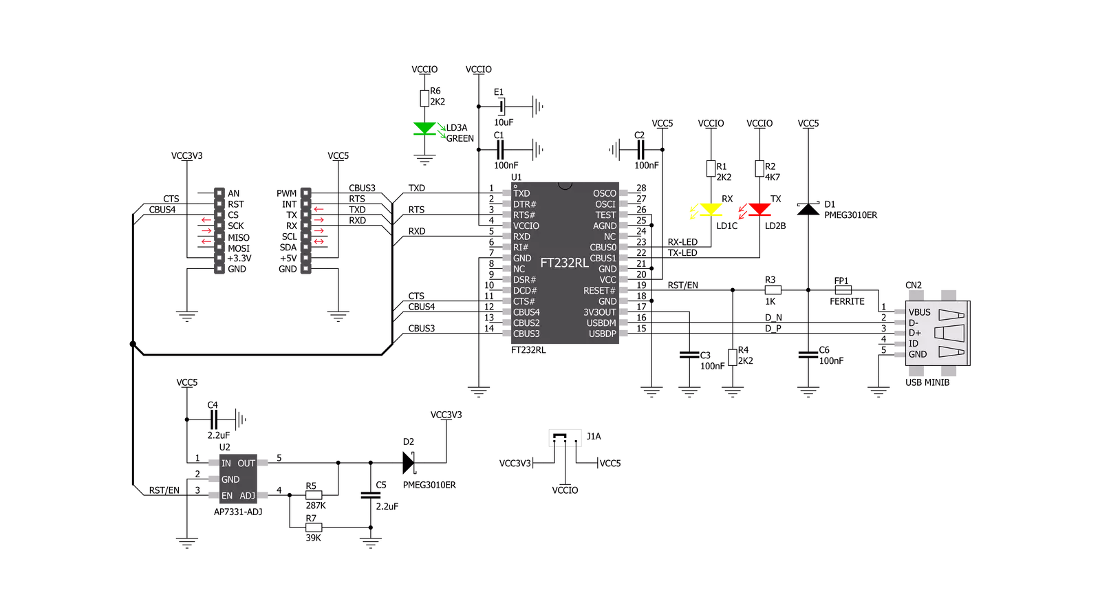
USB UART Click is based on the FT232RL, a USB to serial UART bridge from FTDI Chip. The entire USB protocol is handled on the IC; thus, no USB-specific firmware programming is required. FTDI provides royalty-free Virtual Com Port (VCP) and Direct (D2XX) drivers for all the major OSes used on personal computers. FT232RL also contains an integrated 1024-bit internal EEPROM for storing USB VID, PID, serial number, product description strings, and CBUS I/O configuration. After installing the OS drivers, the device is ready to be used. Plugging into the PC over the mini-USB connector will create a virtual COM port. The Baud Rate Generator provides a 16x clock input to the UART Controller from the 48MHz reference clock. This determines the baud rate of the UART, which is programmable from 183 baud to 3 Mbaud.
Also, non-standard baud rates are supported. The FTDI driver automatically calculates the baud rate, so it is enough to forward the desired baud rate to the driver, usually done by selecting the baud rate via the GUI interface of the PC terminal application. USB UART Click uses a standard 2-Wire UART interface to communicate with the host MCU, with commonly used UART RX and TX pins. In addition, you can use the UART flow control pins RTS and CTS. LEDs RX and TX are here for visual presentation of data flow. This device also features configurable CBUS pins, which can be used for several useful functions, such as configurable clock out for driving the microcontroller, data LED drive, USB Sleep, PWR status, and more. By default, CBUS3 and CBUS4 pins are configured as Power Enable (PWR) and Sleep options (SLP). CBUS3
output pin will be set to a LOW logic state during the USB suspend mode. It can power down external circuitry or be used for similar purposes. CBUS4 output pin will be set to a LOW logic state after the USB has configured the device, then HIGH during the USB suspend mode. This can also be used for powering down/power saving by turning unneeded external circuitry. This Click board™ can operate with either 3.3V or 5V logic voltage levels selected via the I/O LEVEL SEL jumper. This way, both 3.3V and 5V capable MCUs can use the communication lines properly. Also, this Click board™ comes equipped with a library containing easy-to-use functions and an example code that can be used as a reference for further development.

Features overview
Development board
PIC32MZ Clicker is a compact starter development board that brings the flexibility of add-on Click boards™ to your favorite microcontroller, making it a perfect starter kit for implementing your ideas. It comes with an onboard 32-bit PIC32MZ microcontroller with FPU from Microchip, a USB connector, LED indicators, buttons, a mikroProg connector, and a header for interfacing with external electronics. Thanks to its compact design with clear and easy-recognizable silkscreen markings, it provides a fluid and immersive working experience, allowing access anywhere and under
any circumstances. Each part of the PIC32MZ Clicker development kit contains the components necessary for the most efficient operation of the same board. In addition to the possibility of choosing the PIC32MZ Clicker programming method, using USB HID mikroBootloader, or through an external mikroProg connector for PIC, dsPIC, or PIC32 programmer, the Clicker board also includes a clean and regulated power supply module for the development kit. The USB Micro-B connection can provide up to 500mA of current, which is more than enough to operate all onboard
and additional modules. All communication methods that mikroBUS™ itself supports are on this board, including the well-established mikroBUS™ socket, reset button, and several buttons and LED indicators. PIC32MZ Clicker is an integral part of the Mikroe ecosystem, allowing you to create a new application in minutes. Natively supported by Mikroe software tools, it covers many aspects of prototyping thanks to a considerable number of different Click boards™ (over a thousand boards), the number of which is growing every day.

Microcontroller Overview
MCU Card / MCU

Architecture
PIC32
MCU Memory (KB)
1024
Silicon Vendor
Microchip
Pin count
64
RAM (Bytes)
524288
Used MCU Pins
mikroBUS™ mapper
Take a closer look
Click board™ Schematic
Step by step
Project assembly

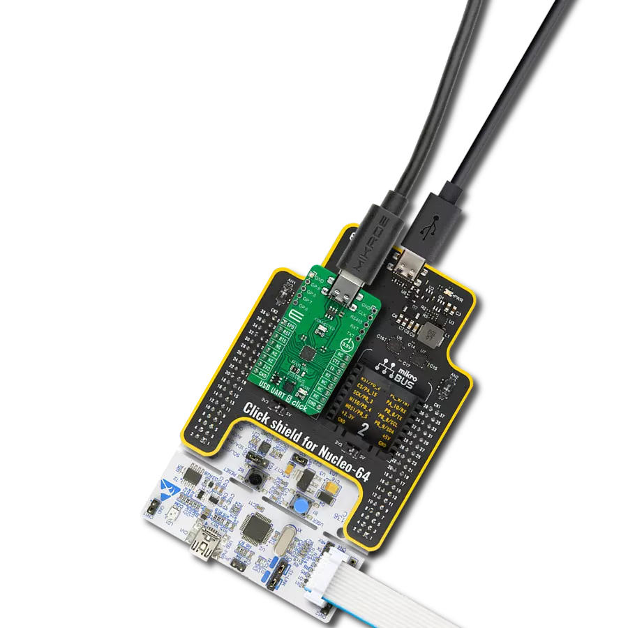
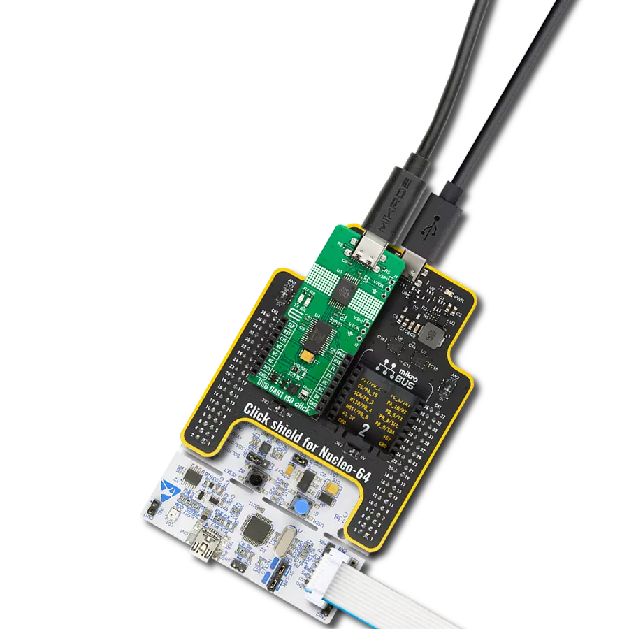
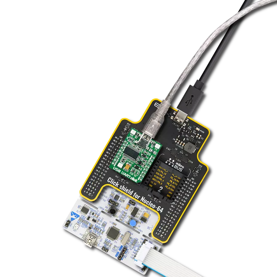
Start by selecting your development board and Click board™. Begin with the PIC32MZ clicker as your development board.


Software Support
Library Description
This library contains API for USB UART Click driver.
Key functions:
usbuart_pwr_ctrl- This function sets the click turns click on.usbuart_set_cts- This function sets CTS pin.usbuart_send_command- This function is used for sending commands.
Open Source
Code example
The complete application code and a ready-to-use project are available through the NECTO Studio Package Manager for direct installation in the NECTO Studio. The application code can also be found on the MIKROE GitHub account.
/*!
 * @file main.c
 * @brief USB UART Click Example.
 *
 *# Description
 * This example reads and processes data from USB UART Clicks.
 *
 * The demo application is composed of two sections :
 *
 * ## Application Init
 * Initializes driver and power module.
 *
 * ## Application Task
 * Reads data and echos it back to device and logs it to board.
 *
 * @author Stefan Ilic
 *
 */

#include "board.h"
#include "log.h"
#include "usbuart.h"
#include "string.h"

#define PROCESS_BUFFER_SIZE 100

static usbuart_t usbuart;
static log_t logger;

static char app_buf[ PROCESS_BUFFER_SIZE ] = { 0 };
static int32_t app_buf_len = 0;

void application_init ( void ) {
    log_cfg_t log_cfg;  /**< Logger config object. */
    usbuart_cfg_t usbuart_cfg;  /**< Click config object. */

    /**
     * Logger initialization.
     * Default baud rate: 115200
     * Default log level: LOG_LEVEL_DEBUG
     * @note If USB_UART_RX and USB_UART_TX
     * are defined as HAL_PIN_NC, you will
     * need to define them manually for log to work.
     * See @b LOG_MAP_USB_UART macro definition for detailed explanation.
     */
    LOG_MAP_USB_UART( log_cfg );
    log_init( &logger, &log_cfg );
    log_info( &logger, " Application Init " );
    Delay_ms ( 100 );

    // Click initialization.

    usbuart_cfg_setup( &usbuart_cfg );
    USBUART_MAP_MIKROBUS( usbuart_cfg, MIKROBUS_1 );

    err_t init_flag  = usbuart_init( &usbuart, &usbuart_cfg );
    if ( UART_ERROR == init_flag ) {
        log_error( &logger, " Application Init Error. " );
        log_info( &logger, " Please, run program again... " );

        for ( ; ; );
    }

    app_buf_len = 0;

    usbuart_pwr_ctrl( &usbuart, USBUART_POWER_ON );
    usbuart_set_cts( &usbuart, USBUART_CTS_NO_ACTIVE );
    usbuart_set_mode( &usbuart, USBUART_MODE_NORMAL );

    log_info( &logger, " Application Task " );
}

void application_task ( void ) {
    app_buf_len = usbuart_generic_read( &usbuart, app_buf, PROCESS_BUFFER_SIZE );

    if ( app_buf_len > 0 ) {
        log_printf( &logger, "%s", app_buf );
        memset( app_buf, 0, PROCESS_BUFFER_SIZE );
    }
}

int main ( void )
{
    /* Do not remove this line or clock might not be set correctly. */
    #ifdef PREINIT_SUPPORTED
    preinit();
    #endif

    application_init( );

    for ( ; ; )
    {
        application_task( );
    }

    return 0;
}

// ------------------------------------------------------------------------ END