Enhance the user experience with customizable lighting effects with the LP5812 and PIC32MZ1024EFH064
Bring dynamic and customizable lighting effects to your projects with four RGB LEDs

Published Jul 02, 2024
Click board™
1x4 RGB Click
Dev. board
PIC32MZ clicker
Compiler
NECTO Studio
MCU
PIC32MZ1024EFH064
Create status indicators, visual cues, and feedback through color-coded lighting in various applications
A
A
Hardware Overview
How does it work?
1x4 RGB Click is based on the LP5812, an advanced RGB LED driver from Texas Instruments. This component manages four onboard RGB LEDs (CLV1A-FKB-CJ1M1F1BB7R4S3) with an autonomous animation engine. The LP5812 features an ultra-low operation current of about 0.4mA in Active mode at a maximum LED current setting of 25.5mA. When all LEDs are off, the device enters Standby mode to minimize power consumption while retaining data. Its autonomous animation engine allows for vivid and dynamic lighting effects without needing brightness control commands from the controller, making it ideal for applications in portable and wearable electronics, gaming, home entertainment, IoT, networking, and industrial HMI. 1x4 RGB Click is designed in a unique format supporting the newly introduced
MIKROE feature called "Click Snap." Unlike the standardized version of Click boards, this feature allows the main IC area to become movable by breaking the PCB, opening up many new possibilities for implementation. Thanks to the Snap feature, the LP5812 can operate autonomously by accessing its signals directly on the pins marked 1-8. Additionally, the Snap part includes a specified and fixed screw hole position, enabling users to secure the Snap board in their desired location. This Click board™ uses a standard 2-wire I2C interface to communicate with the host MCU, supporting Fast mode Plus with up to 1MHz of frequency clock. It also supports both analog and PWM dimming. Analog dimming offers 256 steps for adjusting the output current of each LED, while PWM dimming, enabled by an 8-bit configurable
PWM generator, ensures smooth brightness control. The SYC pin can serve as a PWM clock input or output, allowing multiple 1x4 RGB Click boards to synchronize their animations using a single clock signal from one of the LP5812 devices or an external controller. For enhanced visual performance, optional exponential PWM dimming can be activated for individual LEDs, providing a more human-eye-friendly experience. This Click board™ can operate with either 3.3V or 5V logic voltage levels selected via the VCC SEL jumper. This way, both 3.3V and 5V capable MCUs can use the communication lines properly. Also, this Click board™ comes equipped with a library containing easy-to-use functions and an example code that can be used as a reference for further development.

Features overview
Development board
PIC32MZ Clicker is a compact starter development board that brings the flexibility of add-on Click boards™ to your favorite microcontroller, making it a perfect starter kit for implementing your ideas. It comes with an onboard 32-bit PIC32MZ microcontroller with FPU from Microchip, a USB connector, LED indicators, buttons, a mikroProg connector, and a header for interfacing with external electronics. Thanks to its compact design with clear and easy-recognizable silkscreen markings, it provides a fluid and immersive working experience, allowing access anywhere and under
any circumstances. Each part of the PIC32MZ Clicker development kit contains the components necessary for the most efficient operation of the same board. In addition to the possibility of choosing the PIC32MZ Clicker programming method, using USB HID mikroBootloader, or through an external mikroProg connector for PIC, dsPIC, or PIC32 programmer, the Clicker board also includes a clean and regulated power supply module for the development kit. The USB Micro-B connection can provide up to 500mA of current, which is more than enough to operate all onboard
and additional modules. All communication methods that mikroBUS™ itself supports are on this board, including the well-established mikroBUS™ socket, reset button, and several buttons and LED indicators. PIC32MZ Clicker is an integral part of the Mikroe ecosystem, allowing you to create a new application in minutes. Natively supported by Mikroe software tools, it covers many aspects of prototyping thanks to a considerable number of different Click boards™ (over a thousand boards), the number of which is growing every day.

Microcontroller Overview
MCU Card / MCU

Architecture
PIC32
MCU Memory (KB)
1024
Silicon Vendor
Microchip
Pin count
64
RAM (Bytes)
524288
Used MCU Pins
mikroBUS™ mapper
Take a closer look
Click board™ Schematic

Step by step
Project assembly

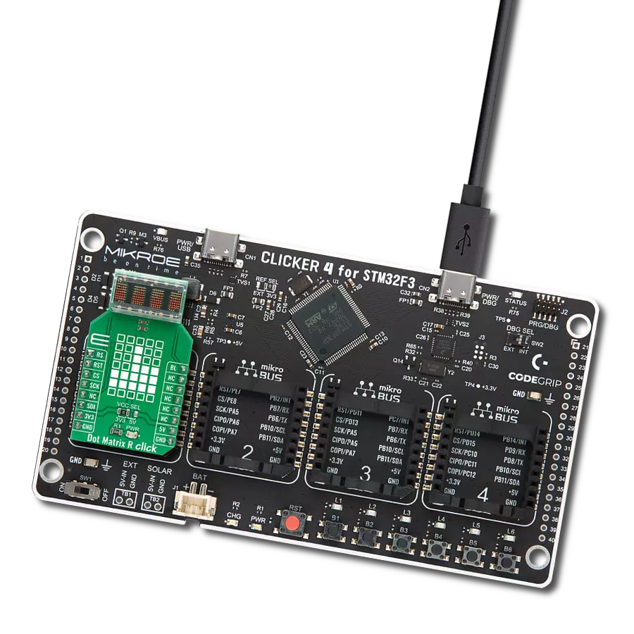
Start by selecting your development board and Click board™. Begin with the PIC32MZ clicker as your development board.


Software Support
Library Description
This library contains API for 1x4 RGB Click driver.
Key functions:
c1x4rgb_set_rgb_color- This function sets the desired values of RGB colors for the selected LED by using the I2C serial interface.c1x4rgb_enable_leds- This function turns on the desired LEDs by using the I2C serial interface.c1x4rgb_set_tmc_mode- This function configures the desired LED drive mode as TCM 1/2/3/4 scans using the I2C serial interface.
Open Source
Code example
The complete application code and a ready-to-use project are available through the NECTO Studio Package Manager for direct installation in the NECTO Studio. The application code can also be found on the MIKROE GitHub account.
/*!
 * @file main.c
 * @brief 1x4 RGB Click example
 *
 * # Description
 * This example demonstrates the use of the 1x4 RGB Click board
 * by controlling the color of the LEDs [LD1-LD4].
 *
 * The demo application is composed of two sections :
 *
 * ## Application Init
 * Initialization of I2C module and log UART.
 * After driver initialization, the app executes a default configuration.
 *
 * ## Application Task
 * The demo example shows the color change of four RGB LEDs,
 * starting with red color, through green and blue, and ending with white.
 * These LEDs actually consist of three single-colored LEDs
 * (Red-Green-Blue) in a single package.
 * Various colors can be reproduced by mixing the intensity of each LED.
 *
 * @author Nenad Filipovic
 *
 */

#include "board.h"
#include "log.h"
#include "c1x4rgb.h"

static c1x4rgb_t c1x4rgb;
static log_t logger;

// Demo RGB color intensity
#define DEMO_COLOR_INT_0        0
#define DEMO_COLOR_INT_100      100

void application_init ( void )
{
    log_cfg_t log_cfg;  /**< Logger config object. */
    c1x4rgb_cfg_t c1x4rgb_cfg;  /**< Click config object. */

    /**
     * Logger initialization.
     * Default baud rate: 115200
     * Default log level: LOG_LEVEL_DEBUG
     * @note If USB_UART_RX and USB_UART_TX
     * are defined as HAL_PIN_NC, you will
     * need to define them manually for log to work.
     * See @b LOG_MAP_USB_UART macro definition for detailed explanation.
     */
    LOG_MAP_USB_UART( log_cfg );
    log_init( &logger, &log_cfg );
    log_info( &logger, " Application Init " );

    // Click initialization.
    c1x4rgb_cfg_setup( &c1x4rgb_cfg );
    C1X4RGB_MAP_MIKROBUS( c1x4rgb_cfg, MIKROBUS_1 );
    if ( I2C_MASTER_ERROR == c1x4rgb_init( &c1x4rgb, &c1x4rgb_cfg ) )
    {
        log_error( &logger, " Communication init." );
        for ( ; ; );
    }

    if ( C1X4RGB_ERROR == c1x4rgb_default_cfg ( &c1x4rgb ) )
    {
        log_error( &logger, " Default configuration." );
        for ( ; ; );
    }

    log_info( &logger, " Application Task " );
    Delay_ms ( 1000 );
}

void application_task ( void )
{
    log_printf( &logger, "\r\n\n RED: " );
    for ( uint8_t led_pos = C1X4RGB_LED_POS_LD1; led_pos <= C1X4RGB_LED_POS_LD4; led_pos++ )
    {
        if ( C1X4RGB_OK == c1x4rgb_set_rgb_color( &c1x4rgb, led_pos, DEMO_COLOR_INT_100,
                                                                     DEMO_COLOR_INT_0,
                                                                     DEMO_COLOR_INT_0 ) )
        {
            log_printf( &logger, " LD%d ", ( uint16_t ) led_pos );
            Delay_ms ( 100 );
        }
    }

    log_printf( &logger, "\r\n GREEN: " );
    for ( uint8_t led_pos = C1X4RGB_LED_POS_LD1; led_pos <= C1X4RGB_LED_POS_LD4; led_pos++ )
    {
        if ( C1X4RGB_OK == c1x4rgb_set_rgb_color( &c1x4rgb, led_pos, DEMO_COLOR_INT_0,
                                                                     DEMO_COLOR_INT_100,
                                                                     DEMO_COLOR_INT_0 ) )
        {
            log_printf( &logger, " LD%d ", ( uint16_t ) led_pos );
            Delay_ms ( 100 );
        }
    }

    log_printf( &logger, "\r\n BLUE: " );
    for ( uint8_t led_pos = C1X4RGB_LED_POS_LD1; led_pos <= C1X4RGB_LED_POS_LD4; led_pos++ )
    {
        if ( C1X4RGB_OK == c1x4rgb_set_rgb_color( &c1x4rgb, led_pos, DEMO_COLOR_INT_0,
                                                                     DEMO_COLOR_INT_0,
                                                                     DEMO_COLOR_INT_100 ) )
        {
            log_printf( &logger, " LD%d ", ( uint16_t ) led_pos );
            Delay_ms ( 100 );
        }
    }

    log_printf( &logger, "\r\n WHITE:" );
    for ( uint8_t led_pos = C1X4RGB_LED_POS_LD1; led_pos <= C1X4RGB_LED_POS_LD4; led_pos++ )
    {
        if ( C1X4RGB_OK == c1x4rgb_set_rgb_color( &c1x4rgb, led_pos, DEMO_COLOR_INT_100,
                                                                     DEMO_COLOR_INT_100,
                                                                     DEMO_COLOR_INT_100 ) )
        {
            log_printf( &logger, " LD%d ", ( uint16_t ) led_pos );
            Delay_ms ( 100 );
        }
    }
}

int main ( void )
{
    /* Do not remove this line or clock might not be set correctly. */
    #ifdef PREINIT_SUPPORTED
    preinit();
    #endif

    application_init( );

    for ( ; ; )
    {
        application_task( );
    }

    return 0;
}

// ------------------------------------------------------------------------ END
Additional Support
Resources
Category:LED Matrix