Unleash the voltage step-down wizardry with MP2316 and PIC32MZ1024EFH064
Ride the wave of efficiency

Published Aug 01, 2023
Click board™
Buck 20 Click
Dev. board
PIC32MZ clicker
Compiler
NECTO Studio
MCU
PIC32MZ1024EFH064
By ensuring precise voltage regulation, this buck converter enhances the reliability and longevity of electronic systems, reducing the risk of voltage-related failures
A
A
Hardware Overview
How does it work?
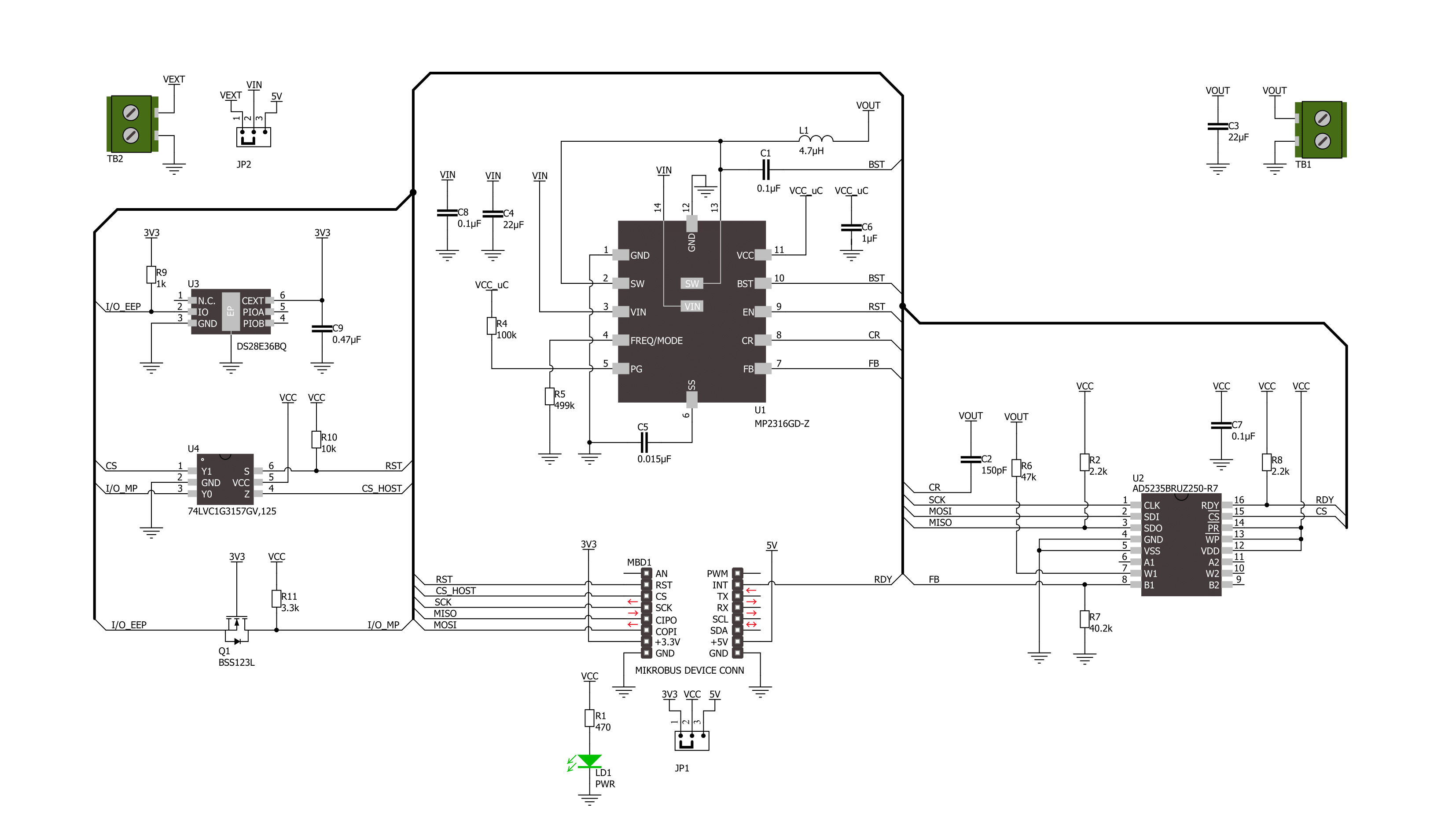
Buck 20 Click is based on the MP2316, a fully-integrated, synchronous, rectified, step-down switch converter from Monolithic Power Systems (MPS). The MP2316 uses constant-on-time (COT) control to provide a fast transient response and easy loop compensation. It achieves 3A continuous output current over a wide input supply range and has excellent load and line regulation. In addition, it is characterized by high efficiency over a wide range of load output voltage, which can be easily adjusted using a digital potentiometer, the AD5235 from Analog Devices. This Click board™ is suitable for battery-operated applications offering advanced protection features such
as undervoltage, overcurrent, short-circuit detection, and thermal shutdown. Thanks to the AD5235 digital potentiometer, this Click board™ can select a decreased output voltage in the range from 1.3V to 5V, with the appropriate command sent via the SPI serial interface. Also, the AD5235 uses a ready RDY pin, routed to the INT pin of the mikroBUS™ socket, for its instruction completion indication. In addition to the SPI interface, the Buck 20 Click also has a device-enable feature, routed to the RST pin of the mikroBUS™ socket, for power ON/OFF purposes optimizing power consumption (converter operation permission). This Click board™ can operate with both 3.3V and
5V logic voltage levels selected via the VCC SEL jumper. This way, both 3.3V and 5V MCUs can use the communication lines correctly. Additionally, there is a possibility for the MP2316 power supply selection via jumper labeled as VIN SEL to supply the MP2316 from an external power supply terminal in the range from 4V to 19V or with mikroBUS™ power rails. However, the Click board™ comes equipped with a library containing easy-to-use functions and an example code that can be used, as a reference, for further development.

Features overview
Development board
PIC32MZ Clicker is a compact starter development board that brings the flexibility of add-on Click boards™ to your favorite microcontroller, making it a perfect starter kit for implementing your ideas. It comes with an onboard 32-bit PIC32MZ microcontroller with FPU from Microchip, a USB connector, LED indicators, buttons, a mikroProg connector, and a header for interfacing with external electronics. Thanks to its compact design with clear and easy-recognizable silkscreen markings, it provides a fluid and immersive working experience, allowing access anywhere and under
any circumstances. Each part of the PIC32MZ Clicker development kit contains the components necessary for the most efficient operation of the same board. In addition to the possibility of choosing the PIC32MZ Clicker programming method, using USB HID mikroBootloader, or through an external mikroProg connector for PIC, dsPIC, or PIC32 programmer, the Clicker board also includes a clean and regulated power supply module for the development kit. The USB Micro-B connection can provide up to 500mA of current, which is more than enough to operate all onboard
and additional modules. All communication methods that mikroBUS™ itself supports are on this board, including the well-established mikroBUS™ socket, reset button, and several buttons and LED indicators. PIC32MZ Clicker is an integral part of the Mikroe ecosystem, allowing you to create a new application in minutes. Natively supported by Mikroe software tools, it covers many aspects of prototyping thanks to a considerable number of different Click boards™ (over a thousand boards), the number of which is growing every day.

Microcontroller Overview
MCU Card / MCU

Architecture
PIC32
MCU Memory (KB)
1024
Silicon Vendor
Microchip
Pin count
64
RAM (Bytes)
524288
Used MCU Pins
mikroBUS™ mapper
Take a closer look
Click board™ Schematic
Step by step
Project assembly

Start by selecting your development board and Click board™. Begin with the PIC32MZ clicker as your development board.


Software Support
Library Description
This library contains API for Buck 20 Click driver.
Key functions:
buck20_set_wiper_1- This function sets wiper 1 to desired valuebuck20_enable_device- This function enables the buck device by setting the RST pin to high logic statebuck20_disable_device- This function disables the buck device by setting the RST pin to low logic state
Open Source
Code example
The complete application code and a ready-to-use project are available through the NECTO Studio Package Manager for direct installation in the NECTO Studio. The application code can also be found on the MIKROE GitHub account.
/*!
 * @file main.c
 * @brief Buck 20 Click example
 *
 * # Description
 * This example demonstrates the use of Buck 20 Click by changing the output voltage.
 *
 * The demo application is composed of two sections :
 *
 * ## Application Init
 * Initializes the driver and enables the device.
 *
 * ## Application Task
 * Changes the output voltage every 3 seconds and displays on the USB UART the digipot
 * wiper position, as well as an approximate buck R1 and voltage output.
 *
 * @note
 * An approximate buck R1 and VOUT values do not have to be 100% accurate for all wiper settings
 * but they are a good reference point. VOUT ranges from ~1.3V to ~5V, and it is the most accurate
 * around 3.3V since all passive components are set for that output.
 *
 * @author Stefan Filipovic
 *
 */

#include "board.h"
#include "log.h"
#include "buck20.h"

static buck20_t buck20;
static log_t logger;

void application_init ( void )
{
    log_cfg_t log_cfg;  /**< Logger config object. */
    buck20_cfg_t buck20_cfg;  /**< Click config object. */

    /**
     * Logger initialization.
     * Default baud rate: 115200
     * Default log level: LOG_LEVEL_DEBUG
     * @note If USB_UART_RX and USB_UART_TX
     * are defined as HAL_PIN_NC, you will
     * need to define them manually for log to work.
     * See @b LOG_MAP_USB_UART macro definition for detailed explanation.
     */
    LOG_MAP_USB_UART( log_cfg );
    log_init( &logger, &log_cfg );
    log_info( &logger, " Application Init " );

    // Click initialization.
    buck20_cfg_setup( &buck20_cfg );
    BUCK20_MAP_MIKROBUS( buck20_cfg, MIKROBUS_1 );
    if ( SPI_MASTER_ERROR == buck20_init( &buck20, &buck20_cfg ) )
    {
        log_error( &logger, " Communication init." );
        for ( ; ; );
    }
    buck20_set_wiper_1 ( &buck20, BUCK20_WIPER_ZERO_SCALE );
    buck20_enable_device ( &buck20 );
    log_info( &logger, " Application Task " );
}

void application_task ( void )
{
    static uint16_t digipot_wiper = BUCK20_WIPER_ZERO_SCALE;
    float buck_r1_kohm, buck_vout;
    if ( BUCK20_OK == buck20_set_wiper_1 ( &buck20, digipot_wiper ) )
    {
        buck_r1_kohm = BUCK20_RESISTOR_R6_KOHM +
                       ( float ) ( BUCK20_DIGIPOT_MAX_KOHM * digipot_wiper ) / BUCK20_WIPER_FULL_SCALE;
        buck_vout = BUCK20_BUCK_VREF + ( buck_r1_kohm * BUCK20_BUCK_VREF ) / BUCK20_BUCK_R2_KOHM;
        log_printf( &logger, " Digipot wiper position: %u\r\n", digipot_wiper );
        log_printf( &logger, " Approximate R1 (Digipot+R6): %.2f kOhm\r\n", buck_r1_kohm );
        log_printf( &logger, " Approximate buck voltage output: %.2f V\r\n\n", buck_vout );
        digipot_wiper += 50;
        if ( digipot_wiper > BUCK20_WIPER_FULL_SCALE )
        {
            digipot_wiper = BUCK20_WIPER_ZERO_SCALE;
        }
    }
    Delay_ms ( 1000 );
    Delay_ms ( 1000 );
    Delay_ms ( 1000 );
}

int main ( void )
{
    /* Do not remove this line or clock might not be set correctly. */
    #ifdef PREINIT_SUPPORTED
    preinit();
    #endif

    application_init( );

    for ( ; ; )
    {
        application_task( );
    }

    return 0;
}

// ------------------------------------------------------------------------ END


