Harness real-time pressure, humidity, and temperature data with MS8607 and PIC32MZ1024EFH064
Your complete PHT measurement solution!

Published Aug 25, 2023
Click board™
PHT Click
Dev. board
PIC32MZ clicker
Compiler
NECTO Studio
MCU
PIC32MZ1024EFH064
Gain a competitive edge by utilizing accurate PHT measurements to monitor and adjust manufacturing conditions, resulting in improved product quality and streamlined production
A
A
Hardware Overview
How does it work?
PHT Click is based on the MS8607, a digital combination sensor providing three environmental measurements: pressure, humidity, and temperature from TE Connectivity. The MS8607 includes two sensors based on MEMS technologies that measure pressure, humidity, and temperature. The first is a piezo-resistive sensor providing pressure and temperature measurements, and the second is a capacitive humidity sensor providing relative humidity measurement. Each sensor is interfaced to a ΔΣ ADC integrated circuit for digital conversion. The MS8607 converts analog output voltages to a 24-bit digital value for the pressure and temperature measurements and a 12-bit digital value for the
relative humidity measurement. Pressure measurement accuracy comes in at +/- 2mbar, relative humidity at +/- 3% RH, and the temperature within 1°C. One standout feature of the MS8607 is its very respectable low power consumption at as low as 0.78 µA. Perfect for sensing general weather conditions, the MS8607 shines for high-altitude, low-pressure applications. Capable of sensing down to 10 bar, the MS8607 is simple to use and gives the user some powerful readings with very little power and conversion time. PHT Click communicates with MCU using the standard I2C 2-Wire interface with a maximum clock frequency of 400kHz. Since the sensor is supplied with 3.3V logic voltage level only, also
featured on this Click board™ is a PCA9306 voltage-level translator from Texas Instruments. The I2C interface bus lines are routed to the dual bidirectional voltage-level translator, allowing this Click board™ to be interfaced with both 3.3V and 5V MCUs. This Click board™ can operate with either 3.3V or 5V logic voltage levels selected via the VCC SEL jumper. This way, both 3.3V and 5V capable MCUs can use the communication lines properly. Also, this Click board™ comes equipped with a library containing easy-to-use functions and an example code that can be used, as a reference, for further development.


Features overview
Development board
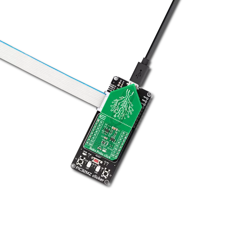
PIC32MZ Clicker is a compact starter development board that brings the flexibility of add-on Click boards™ to your favorite microcontroller, making it a perfect starter kit for implementing your ideas. It comes with an onboard 32-bit PIC32MZ microcontroller with FPU from Microchip, a USB connector, LED indicators, buttons, a mikroProg connector, and a header for interfacing with external electronics. Thanks to its compact design with clear and easy-recognizable silkscreen markings, it provides a fluid and immersive working experience, allowing access anywhere and under
any circumstances. Each part of the PIC32MZ Clicker development kit contains the components necessary for the most efficient operation of the same board. In addition to the possibility of choosing the PIC32MZ Clicker programming method, using USB HID mikroBootloader, or through an external mikroProg connector for PIC, dsPIC, or PIC32 programmer, the Clicker board also includes a clean and regulated power supply module for the development kit. The USB Micro-B connection can provide up to 500mA of current, which is more than enough to operate all onboard
and additional modules. All communication methods that mikroBUS™ itself supports are on this board, including the well-established mikroBUS™ socket, reset button, and several buttons and LED indicators. PIC32MZ Clicker is an integral part of the Mikroe ecosystem, allowing you to create a new application in minutes. Natively supported by Mikroe software tools, it covers many aspects of prototyping thanks to a considerable number of different Click boards™ (over a thousand boards), the number of which is growing every day.

Microcontroller Overview
MCU Card / MCU

Architecture
PIC32
MCU Memory (KB)
1024
Silicon Vendor
Microchip
Pin count
64
RAM (Bytes)
524288
Used MCU Pins
mikroBUS™ mapper
Take a closer look
Click board™ Schematic

Step by step
Project assembly

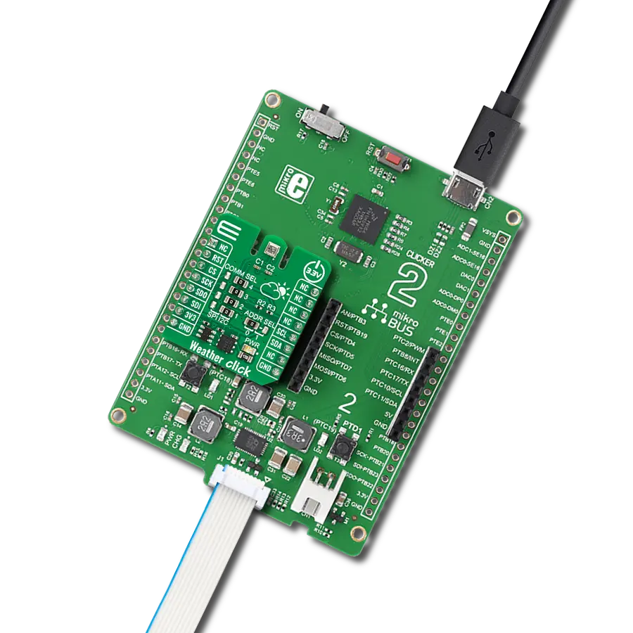
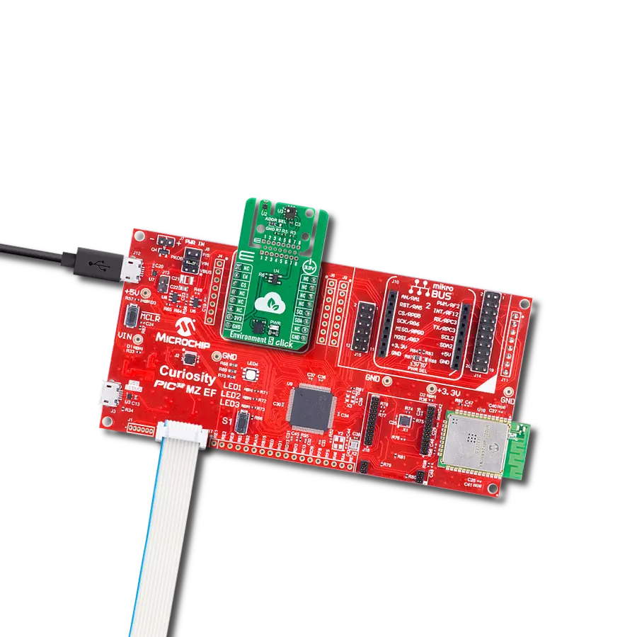
Start by selecting your development board and Click board™. Begin with the PIC32MZ clicker as your development board.


Software Support
Library Description
This library contains API for PHT Click driver.
Key functions:
pht_set_ratio- Set Ratio functionpht_get_temperature_pressure- Get temperature and pressure functionpht_get_relative_humidity- Get humidity function
Open Source
Code example
The complete application code and a ready-to-use project are available through the NECTO Studio Package Manager for direct installation in the NECTO Studio. The application code can also be found on the MIKROE GitHub account.
/*!
 * @file main.c
 * @brief PHT Click example
 *
 * # Description
 * This is an example that demonstrates the use of the PHT Click board.
 *
 * The demo application is composed of two sections :
 *
 * ## Application Init
 * Initialization driver enables - I2C,
 * performs the device reset and determines the oversampling ratio,
 * also write log.
 *
 * ## Application Task
 * PHT Click board can be used to measure Pressure, Temperature
 * and Relative Humidity.
 * All data logs write on USB uart changes every 3 sec.
 *
 *
 * @author Stefan Ilic
 *
 */

#include "board.h"
#include "log.h"
#include "pht.h"

static pht_t pht;
static log_t logger;

float pressure;
float humidity;
float temperature;

void application_init ( void ) {
    log_cfg_t log_cfg;  /**< Logger config object. */
    pht_cfg_t pht_cfg;  /**< Click config object. */

    /**
     * Logger initialization.
     * Default baud rate: 115200
     * Default log level: LOG_LEVEL_DEBUG
     * @note If USB_UART_RX and USB_UART_TX
     * are defined as HAL_PIN_NC, you will
     * need to define them manually for log to work.
     * See @b LOG_MAP_USB_UART macro definition for detailed explanation.
     */
    LOG_MAP_USB_UART( log_cfg );
    log_init( &logger, &log_cfg );
    log_info( &logger, " Application Init " );

    // Click initialization.
    pht_cfg_setup( &pht_cfg );
    PHT_MAP_MIKROBUS( pht_cfg, MIKROBUS_1 );
    err_t init_flag = pht_init( &pht, &pht_cfg );
    if ( I2C_MASTER_ERROR == init_flag ) {
        log_error( &logger, " Application Init Error. " );
        log_info( &logger, " Please, run program again... " );

        for ( ; ; );
    }

    log_printf( &logger, "---------------------------- \r\n " );
    log_printf( &logger, " Device reset \r\n" );
    pht_reset( &pht );
    Delay_ms ( 100 );
    log_printf( &logger, "---------------------------- \r\n " );
    log_printf( &logger, " Set Oversampling Ratio \r\n" );
    pht_set_ratio( &pht, PHT_PT_CMD_RATIO_2048, PHT_PT_CMD_RATIO_2048);
    Delay_ms ( 100 );
    log_printf( &logger, "---------------------------- \r\n " );
    log_info( &logger, " Application Task " );
    log_printf( &logger, "---------------------------- \r\n " );
}

void application_task ( void ) {
    pht_get_temperature_pressure( &pht, &temperature, &pressure );
    Delay_ms ( 10 );
    pht_get_relative_humidity( &pht, &humidity );
    Delay_ms ( 10 );

    log_printf( &logger, " Preassure   : %.2f mbar \r\n ", pressure );
    log_printf( &logger, " Humidity    :  %.2f %% \r\n ", humidity );
    log_printf( &logger, " Temperature :  %.2f C \r\n ", temperature );
    log_printf( &logger, "---------------------------- \r\n " );
    Delay_ms ( 1000 );
    Delay_ms ( 1000 );
    Delay_ms ( 1000 );
}

int main ( void )
{
    /* Do not remove this line or clock might not be set correctly. */
    #ifdef PREINIT_SUPPORTED
    preinit();
    #endif

    application_init( );

    for ( ; ; )
    {
        application_task( );
    }

    return 0;
}

// ------------------------------------------------------------------------ END