Charge Li-Ion or Polymer batteries with nPM1100 and PIC32MZ1024EFH064
Charge smart - charge safe

Published Dec 10, 2023
Click board™
Charger 19 Click
Dev. board
PIC32MZ clicker
Compiler
NECTO Studio
MCU
PIC32MZ1024EFH064
Comprehensive solution for battery charging needs, with a focus on efficiency, versatility, and safety
A
A
Hardware Overview
How does it work?
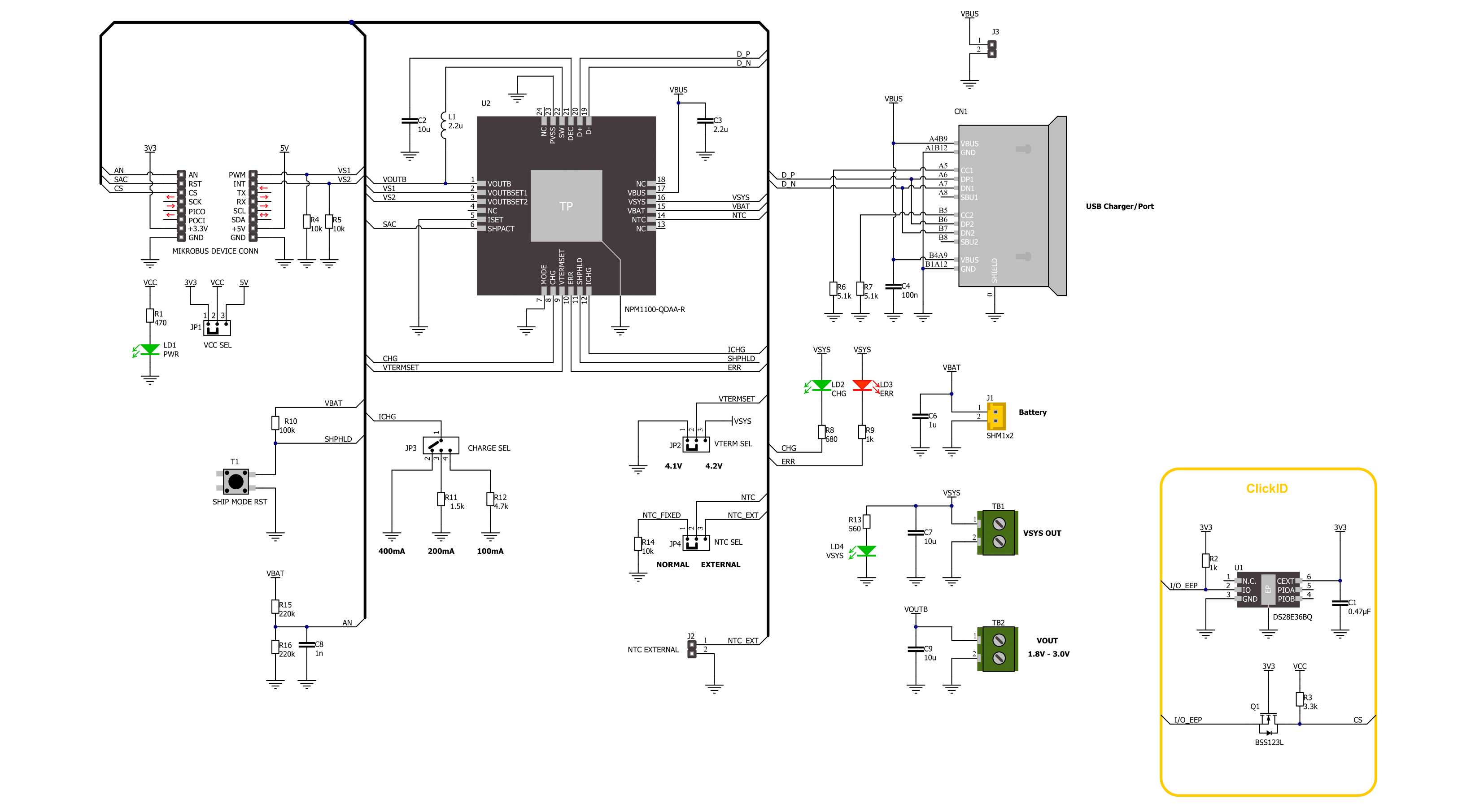
Charger 19 Click is based on the nPM1100, an integrated power management IC from Nordic Semiconductor. It supports charging batteries at up to 400mA. The charging current can be selected over the CHARGE SEL jumper (100, 200, 400mA). The low quiescent current extends battery life for shipping and storage in Ship mode or in operation with auto-controlled hysteretic buck mode for high efficiency down to 1μA loads. The Ship mode isolates the battery, can be activated by the host MCU, and deactivated over the onboard SHIP MODE RST key button or by connecting the Charger 19 Click to a VBUS power supply. The VBUS can be supplied with power over the USB C connector or the VBUS header with a voltage of 4.1 up to 5.5V. The battery can be connected to the BATT connector with properly
labeled polarity. It can also deliver up to 150mA of current to power external components with regulated voltage over the VOUTB terminal. The output voltage can be set in a range of 1.8 – 3.0V by the host MCU, according to the table in the datasheet. There is also a system voltage output terminal VSYS, which is automatically enabled after a power-on reset and indicated by the VSYS LED. In addition, there are CHG and ERR LEDs, which indicate the device's charging status. The nPM1100 implements a thermal regulation based on battery temperature. There is an NTC SEL jumper to choose between the onboard 10K resistor or an external NTC thermistor, which can be connected over the NTC EXT connector. Finally, the termination voltage can be set over the VTERM SEL jumper between 4.1V and 4.2V
(4.1V set by default). Charger 19 Click uses a general purpose IO pins to communicate with the host MCU. The mentioned shipping mode can be activated over the SAC pin. You can always monitor the battery charging level over the analog AN pin and voltage divider. The buck regulator output voltage can be set over the VS1 and VS2 pins, but only when no connected device exists. You can connect the device to VOUTB after you set the output voltage. This Click board™ can operate with either 3.3V or 5V logic voltage levels selected via the VCC SEL jumper. This way, both 3.3V and 5V capable MCUs can use the communication lines properly. Also, this Click board™ comes equipped with a library containing easy-to-use functions and an example code that can be used as a reference for further development.

Features overview
Development board
PIC32MZ Clicker is a compact starter development board that brings the flexibility of add-on Click boards™ to your favorite microcontroller, making it a perfect starter kit for implementing your ideas. It comes with an onboard 32-bit PIC32MZ microcontroller with FPU from Microchip, a USB connector, LED indicators, buttons, a mikroProg connector, and a header for interfacing with external electronics. Thanks to its compact design with clear and easy-recognizable silkscreen markings, it provides a fluid and immersive working experience, allowing access anywhere and under
any circumstances. Each part of the PIC32MZ Clicker development kit contains the components necessary for the most efficient operation of the same board. In addition to the possibility of choosing the PIC32MZ Clicker programming method, using USB HID mikroBootloader, or through an external mikroProg connector for PIC, dsPIC, or PIC32 programmer, the Clicker board also includes a clean and regulated power supply module for the development kit. The USB Micro-B connection can provide up to 500mA of current, which is more than enough to operate all onboard
and additional modules. All communication methods that mikroBUS™ itself supports are on this board, including the well-established mikroBUS™ socket, reset button, and several buttons and LED indicators. PIC32MZ Clicker is an integral part of the Mikroe ecosystem, allowing you to create a new application in minutes. Natively supported by Mikroe software tools, it covers many aspects of prototyping thanks to a considerable number of different Click boards™ (over a thousand boards), the number of which is growing every day.

Microcontroller Overview
MCU Card / MCU

Architecture
PIC32
MCU Memory (KB)
1024
Silicon Vendor
Microchip
Pin count
64
RAM (Bytes)
524288
You complete me!
Accessories
Li-Polymer Battery is the ideal solution for devices that demand a dependable and long-lasting power supply while emphasizing mobility. Its compatibility with mikromedia boards ensures easy integration without additional modifications. With a voltage output of 3.7V, the battery meets the standard requirements of many electronic devices. Additionally, boasting a capacity of 2000mAh, it can store a substantial amount of energy, providing sustained power for extended periods. This feature minimizes the need for frequent recharging or replacement. Overall, the Li-Polymer Battery is a reliable and autonomous power source, ideally suited for devices requiring a stable and enduring energy solution. You can find a more extensive choice of Li-Polymer batteries in our offer.

Used MCU Pins
mikroBUS™ mapper
Take a closer look
Click board™ Schematic
Step by step
Project assembly

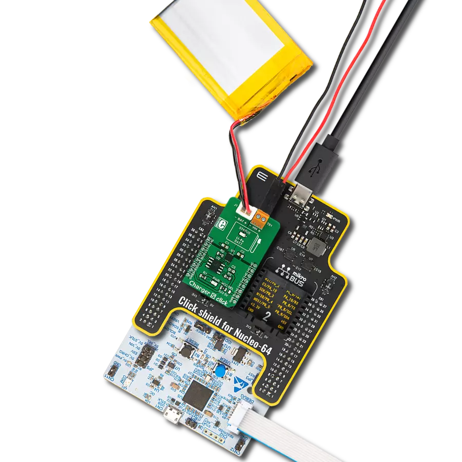
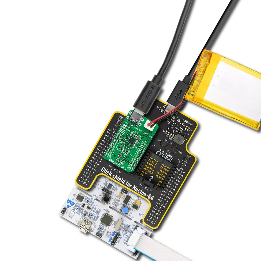
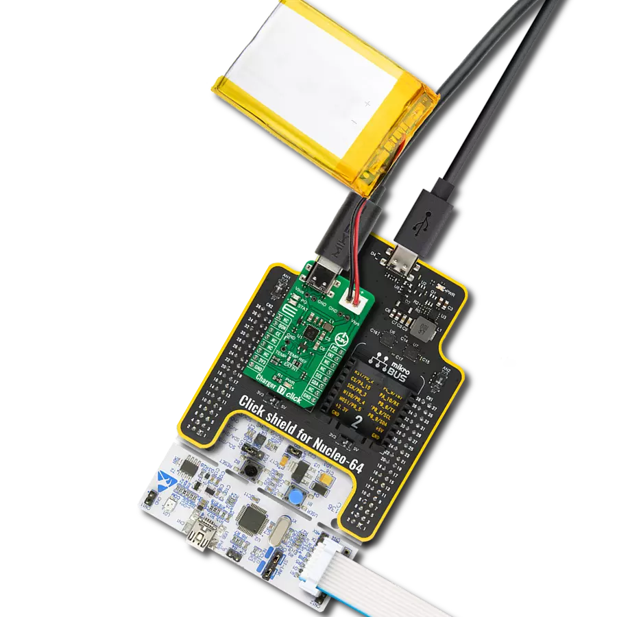
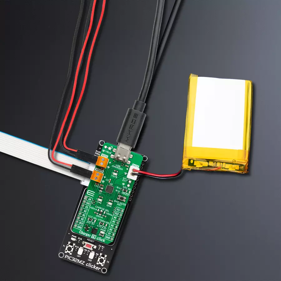
Start by selecting your development board and Click board™. Begin with the PIC32MZ clicker as your development board.


Track your results in real time
Application Output
1. Application Output - In Debug mode, the 'Application Output' window enables real-time data monitoring, offering direct insight into execution results. Ensure proper data display by configuring the environment correctly using the provided tutorial.

2. UART Terminal - Use the UART Terminal to monitor data transmission via a USB to UART converter, allowing direct communication between the Click board™ and your development system. Configure the baud rate and other serial settings according to your project's requirements to ensure proper functionality. For step-by-step setup instructions, refer to the provided tutorial.

3. Plot Output - The Plot feature offers a powerful way to visualize real-time sensor data, enabling trend analysis, debugging, and comparison of multiple data points. To set it up correctly, follow the provided tutorial, which includes a step-by-step example of using the Plot feature to display Click board™ readings. To use the Plot feature in your code, use the function: plot(*insert_graph_name*, variable_name);. This is a general format, and it is up to the user to replace 'insert_graph_name' with the actual graph name and 'variable_name' with the parameter to be displayed.

Software Support
Library Description
This library contains API for Charger 19 Click driver.
Key functions:
charger19_set_vout- Charger 19 set output voltage function.charger19_set_ship_mode- Charger 19 set Ship mode function.charger19_get_vbat- Charger 19 get battery voltage function.
Open Source
Code example
The complete application code and a ready-to-use project are available through the NECTO Studio Package Manager for direct installation in the NECTO Studio. The application code can also be found on the MIKROE GitHub account.
/*!
 * @file main.c
 * @brief Charger 19 Click Example.
 *
 * # Description
 * This example demonstrates the use of Charger 19 Click board by enabling the device
 * and then reading and displaying the battery voltage.
 *
 * The demo application is composed of two sections :
 *
 * ## Application Init
 * Initializes the driver and enables the device, sets the output
 * voltage to 3 V.
 *
 * ## Application Task
 * Tracking charging status, reading battery voltage.
 *
 * @author Stefan Ilic
 *
 */

#include "board.h"
#include "log.h"
#include "charger19.h"

static charger19_t charger19;   /**< Charger 19 Click driver object. */
static log_t logger;            /**< Logger object. */

void application_init ( void )
{
    log_cfg_t log_cfg;              /**< Logger config object. */
    charger19_cfg_t charger19_cfg;  /**< Click config object. */

    /**
     * Logger initialization.
     * Default baud rate: 115200
     * Default log level: LOG_LEVEL_DEBUG
     * @note If USB_UART_RX and USB_UART_TX
     * are defined as HAL_PIN_NC, you will
     * need to define them manually for log to work.
     * See @b LOG_MAP_USB_UART macro definition for detailed explanation.
     */
    LOG_MAP_USB_UART( log_cfg );
    log_init( &logger, &log_cfg );
    log_info( &logger, " Application Init " );

    // Click initialization.
    charger19_cfg_setup( &charger19_cfg );
    CHARGER19_MAP_MIKROBUS( charger19_cfg, MIKROBUS_1 );
    if ( ADC_ERROR == charger19_init( &charger19, &charger19_cfg ) )
    {
        log_error( &logger, " Communication init." );
        for ( ; ; );
    }

    if ( CHARGER19_ERROR == charger19_default_cfg ( &charger19 ) )
    {
        log_error( &logger, " Default configuration." );
        for ( ; ; );
    }

    log_info( &logger, " Application Task " );
}

void application_task ( void )
{
    float voltage = 0;
    if ( CHARGER19_OK == charger19_get_vbat ( &charger19, &voltage ) )
    {
        log_printf( &logger, " Battery Voltage : %.3f[V]\r\n\n", voltage );
        Delay_ms ( 1000 );
    }
}

int main ( void )
{
    /* Do not remove this line or clock might not be set correctly. */
    #ifdef PREINIT_SUPPORTED
    preinit();
    #endif

    application_init( );

    for ( ; ; )
    {
        application_task( );
    }

    return 0;
}

// ------------------------------------------------------------------------ END