Elevate your cooling experience with TC654 and PIC32MZ1024EFH064
Seamlessly adjust fan speeds for a relaxing atmosphere
Published Jul 01, 2023
Click board™
Fan 5 Click
Dev. board
PIC32MZ clicker
Compiler
NECTO Studio
MCU
PIC32MZ1024EFH064
Take control of the perfect airflow with our PWM-mode fan speed controller!
A
A
Hardware Overview
How does it work?
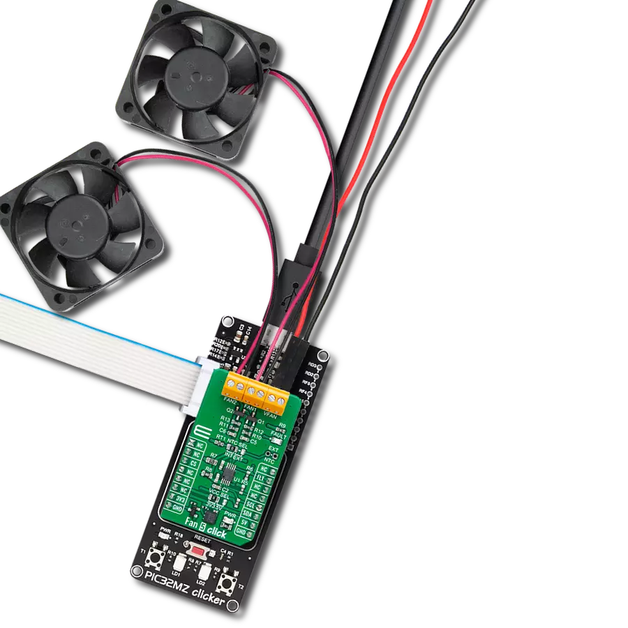
Fan 5 Click is based on the TC654, a fan speed controller from Microchip that allows you to control and monitor the speed of two DC brushless fans. The TC654 is based on the FanSense™ technology, which protects your application against fan failure and eliminates the need for 3-wire fans. With the TC654, the fan speed can be controlled by its input voltage or the serial interface, allowing for high flexibility. The input voltage of the TC654 represents temperature, typically provided by a chosen internal or external thermistor (selected using an NTC SEL jumper). The TC654 controls fan speed according to the system temperature by pulse-width modulating the voltage across the fan. This method reduces the fan'sfan's acoustic noise and extends the fan'sfan's working life. An external N-channel MOSFET, one per channel, controls the
fans. Modulating the voltage applied to the gate of the MOSFETs also modulates the voltage applied to the fan. The PWM output can be adjusted between 30% and 100%, based on the TC654's input voltage, or programmed, as mentioned, via the I2C interface to allow fan speed control without needing an external thermistor. The standard I2C 2-Wire interface reads data and configures settings with a maximum frequency of 100kHz. The TC654 also measures and monitors fan revolutions per minute (RPM), representing a measure of its health. As a fan'sfan's bearings wear out, the fan slows down and eventually stops (locked rotor). The TC654 can detect open, shorted, unconnected, and locked rotor fan conditions by monitoring the fan'sfan's RPM level. Apart from the availability of this information on the FLT pin of the mikroBUS™ socket, this condition can also be
visually detected through the red LED marked with FAULT. The fan RPM data and threshold registers are available over the I2C interface, allowing complete system control. In addition to the two terminals for fan connections, there is another terminal, VFAN, for an external 12V power supply for FAN1. FAN2 uses the necessary supply from the 5V mikroBUS™ power rail. This Click board™ can operate with both 3.3V and 5V logic voltage levels selected via the VCC SEL jumper. This way, both 3.3V and 5V MCUs can use the communication lines correctly. However, the Click board™ comes equipped with a library containing easy-to-use functions and an example code that can be used, as a reference, for further development.

Features overview
Development board
PIC32MZ Clicker is a compact starter development board that brings the flexibility of add-on Click boards™ to your favorite microcontroller, making it a perfect starter kit for implementing your ideas. It comes with an onboard 32-bit PIC32MZ microcontroller with FPU from Microchip, a USB connector, LED indicators, buttons, a mikroProg connector, and a header for interfacing with external electronics. Thanks to its compact design with clear and easy-recognizable silkscreen markings, it provides a fluid and immersive working experience, allowing access anywhere and under
any circumstances. Each part of the PIC32MZ Clicker development kit contains the components necessary for the most efficient operation of the same board. In addition to the possibility of choosing the PIC32MZ Clicker programming method, using USB HID mikroBootloader, or through an external mikroProg connector for PIC, dsPIC, or PIC32 programmer, the Clicker board also includes a clean and regulated power supply module for the development kit. The USB Micro-B connection can provide up to 500mA of current, which is more than enough to operate all onboard
and additional modules. All communication methods that mikroBUS™ itself supports are on this board, including the well-established mikroBUS™ socket, reset button, and several buttons and LED indicators. PIC32MZ Clicker is an integral part of the Mikroe ecosystem, allowing you to create a new application in minutes. Natively supported by Mikroe software tools, it covers many aspects of prototyping thanks to a considerable number of different Click boards™ (over a thousand boards), the number of which is growing every day.

Microcontroller Overview
MCU Card / MCU

Architecture
PIC32
MCU Memory (KB)
1024
Silicon Vendor
Microchip
Pin count
64
RAM (Bytes)
524288
Used MCU Pins
mikroBUS™ mapper
Take a closer look
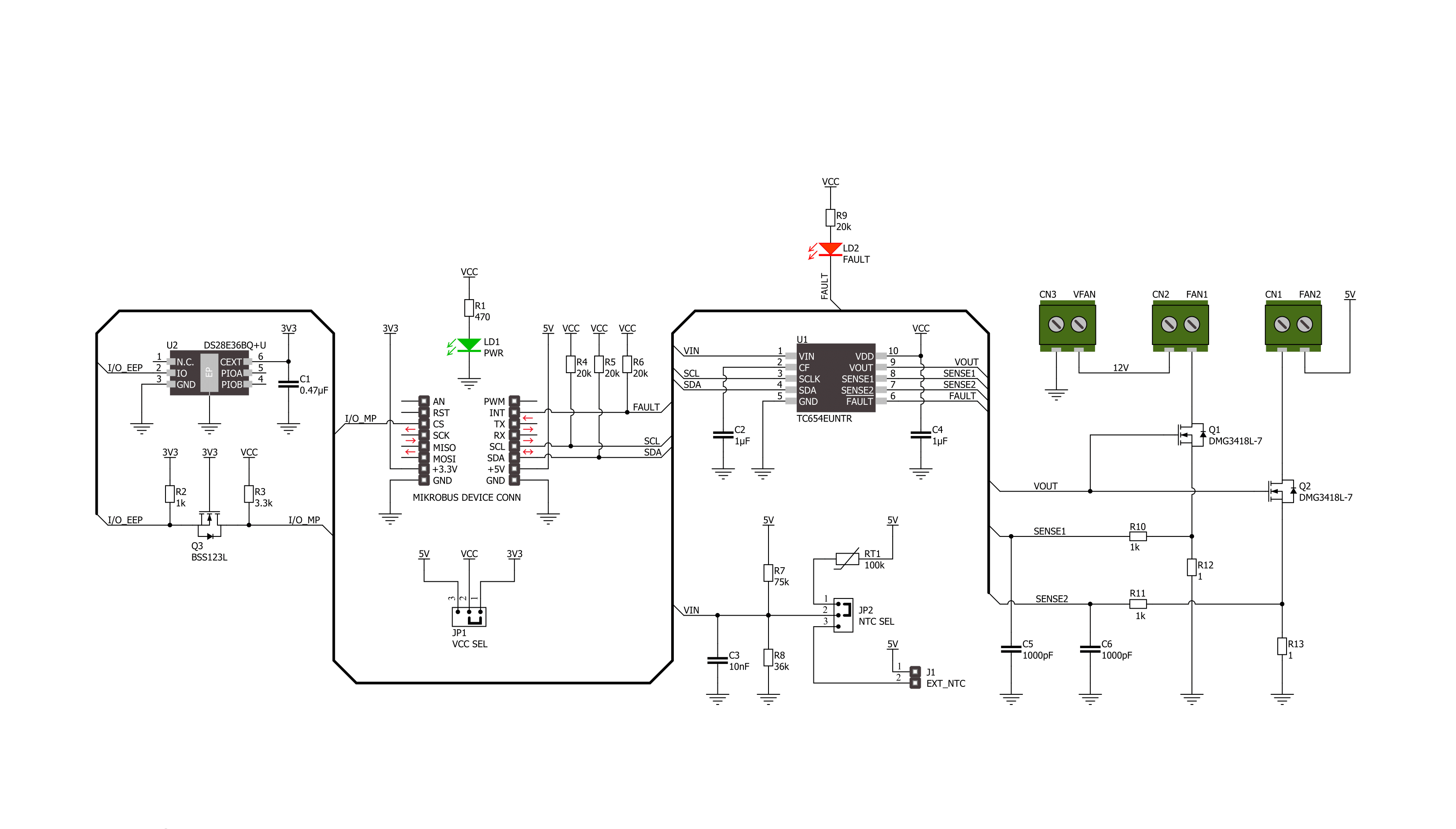
Click board™ Schematic
Step by step
Project assembly

Start by selecting your development board and Click board™. Begin with the PIC32MZ clicker as your development board.


Track your results in real time
Application Output
1. Application Output - In Debug mode, the 'Application Output' window enables real-time data monitoring, offering direct insight into execution results. Ensure proper data display by configuring the environment correctly using the provided tutorial.

2. UART Terminal - Use the UART Terminal to monitor data transmission via a USB to UART converter, allowing direct communication between the Click board™ and your development system. Configure the baud rate and other serial settings according to your project's requirements to ensure proper functionality. For step-by-step setup instructions, refer to the provided tutorial.

3. Plot Output - The Plot feature offers a powerful way to visualize real-time sensor data, enabling trend analysis, debugging, and comparison of multiple data points. To set it up correctly, follow the provided tutorial, which includes a step-by-step example of using the Plot feature to display Click board™ readings. To use the Plot feature in your code, use the function: plot(*insert_graph_name*, variable_name);. This is a general format, and it is up to the user to replace 'insert_graph_name' with the actual graph name and 'variable_name' with the parameter to be displayed.

Software Support
Library Description
This library contains API for Fan 5 Click driver.
Key functions:
fan5_get_rpm1- Fan 5 get speed of FAN1fan5_set_duty_cycle- Fan 5 set duty cyclefan5_turn_on_fans- Fan 5 turn on fans
Open Source
Code example
The complete application code and a ready-to-use project are available through the NECTO Studio Package Manager for direct installation in the NECTO Studio. The application code can also be found on the MIKROE GitHub account.
/*!
 * @file main.c
 * @brief Fan 5 Click example
 *
 * # Description
 * This example demonstrates the use of FAN 5 Click board by controlling and
 * regulating the fan motors speed.
 *
 * The demo application is composed of two sections :
 *
 * ## Application Init
 * Initializes the driver, performs the Click default configuration, reads
 * manufacturer id and sets configuration in correspondence to user-selected mode.
 *
 * ## Application Task
 * If Fan control is selected example will monitor FAN 1 speed and if the speed
 * falls below 500 RPM for longer then 2.4 seconds fan output will be disabled.
 * In other case, example is showcasing speed control by changing duty cycle and
 * monitoring fan speed.
 *
 * @author Stefan Ilic
 *
 */

#include "board.h"
#include "log.h"
#include "fan5.h"

#define FAN_CONTROL_MODE

static fan5_t fan5;
static log_t logger;

void application_init ( void )
{
    log_cfg_t log_cfg;  /**< Logger config object. */
    fan5_cfg_t fan5_cfg;  /**< Click config object. */

    /**
     * Logger initialization.
     * Default baud rate: 115200
     * Default log level: LOG_LEVEL_DEBUG
     * @note If USB_UART_RX and USB_UART_TX
     * are defined as HAL_PIN_NC, you will
     * need to define them manually for log to work.
     * See @b LOG_MAP_USB_UART macro definition for detailed explanation.
     */

    LOG_MAP_USB_UART( log_cfg );
    log_init( &logger, &log_cfg );
    log_info( &logger, " Application Init " );

    // Click initialization.
    fan5_cfg_setup( &fan5_cfg );
    FAN5_MAP_MIKROBUS( fan5_cfg, MIKROBUS_1 );
    if ( I2C_MASTER_ERROR == fan5_init( &fan5, &fan5_cfg ) )
    {
        log_error( &logger, " Communication init." );
        for ( ; ; );
    }

    if ( FAN5_ERROR == fan5_default_cfg ( &fan5 ) )
    {
        log_error( &logger, " Default configuration." );
        for ( ; ; );
    }
    fan5_turn_on_fans( &fan5 );
    uint8_t id = 0;
    fan5_get_mfr_id( &fan5, &id );
    log_printf( &logger, " Manufacturer ID: 0x%X \r\n", ( uint16_t ) id );

#if defined FAN_CONTROL_MODE
    fan5_set_duty_cycle( &fan5, FAN5_100_PER_DUTY );
    fan5_set_fan_fault1( &fan5, 500 );
#else
    fan5_set_duty_cycle( &fan5, FAN5_30_PER_DUTY );
    fan5_set_fan_fault1( &fan5, 0 );
#endif

    log_info( &logger, " Application Task " );
}

void application_task ( void )
{
#if defined FAN_CONTROL_MODE
    uint16_t speed = 0;
    uint8_t flag_data = 0;

    fan5_get_rpm1( &fan5, &speed);
    log_printf( &logger, " SPEED: %d RPM \r\n", speed );

    if ( FAN5_FAULT == fan5_get_fault_state( &fan5 ) )
    {
        fan5_get_status_flags ( &fan5, &flag_data );
        log_printf( &logger, " FLAG: %d \r\n", flag_data );
        if ( FAN5_F1F_FLAG & flag_data )
        {
            log_printf( &logger, " FAN SPEED DROPED !!! \r\n" );
            log_printf( &logger, " OUTPUT IS DISABLED \r\n" );
            fan5_turn_off_fans( &fan5 );
            for( ; ; );
        }
    }

    Delay_ms ( 1000 );
    Delay_ms ( 1000 );
#else
    uint16_t speed;
    uint8_t duty_value;

    for ( duty_value = FAN5_30_PER_DUTY; duty_value <= FAN5_100_PER_DUTY; duty_value++ )
    {
        fan5_set_duty_cycle( &fan5, duty_value );
        log_printf( &logger, " Duty value: %d \r\n", ( uint16_t ) duty_value );
        Delay_ms ( 1000 );
        Delay_ms ( 1000 );
        Delay_ms ( 1000 );
        Delay_ms ( 1000 );
        Delay_ms ( 1000 );
        fan5_get_rpm1( &fan5, &speed);
        log_printf( &logger, " SPEED: %d RPM \r\n", speed );
        Delay_ms ( 500 );
    }
#endif
}

int main ( void )
{
    /* Do not remove this line or clock might not be set correctly. */
    #ifdef PREINIT_SUPPORTED
    preinit();
    #endif

    application_init( );

    for ( ; ; )
    {
        application_task( );
    }

    return 0;
}

// ------------------------------------------------------------------------ END


