Provide a pulse train or a square wave proportional to ambient light intensity with TSL230BR and PIC32MX470F512H
Programmable light-to-frequency converter

Published Mar 09, 2024
Click board™
LightHz Click
Dev. board
6LoWPAN clicker
Compiler
NECTO Studio
MCU
PIC32MX470F512H
Achieve an accurate, high-resolution light intensity measurement in various applications, from basic ambient light sensing to rough color detection
A
A
Hardware Overview
How does it work?
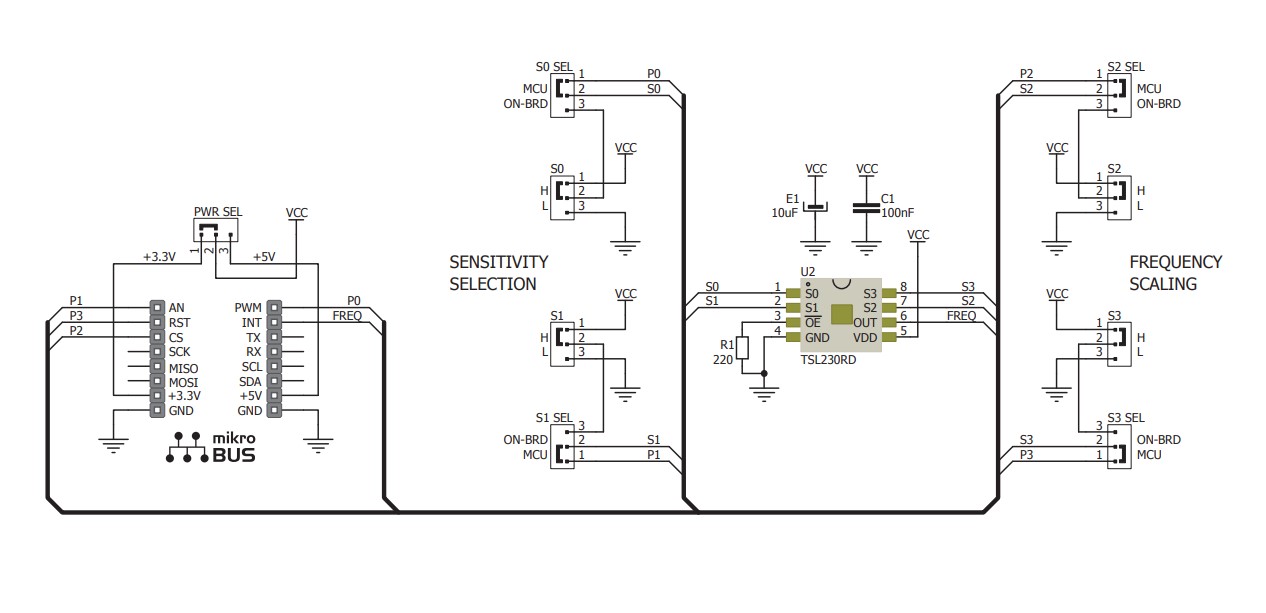
LightHz Click is based on the TSL230BR, a programmable light-to-frequency converter from ams OSRAM. It combines a configurable silicon photodiode and a current-to-frequency converter and has a high-resolution conversion of light intensity with no external components. The sensor responds over the 320nm to 1050nm light range and is temperature-compensated for the ultraviolet-to-visible light range of 320nm to 700nm. Device sensitivity is selectable in three ranges, providing two decades of adjustment, while the full-scale output frequency can be scaled by one of four preset values with 5% absolute tolerance. The LightHz Click uses its frequency output to communicate with the host MCU over the OUT pin of the mikroBUS™ socket. The board comes with four SMD jumpers labeled MCU ON-BRD, which allows you to choose the scaling and sensitivity configuration to be controlled by the host MCU
rather than the onboard jumper selection. The latter is set by default. Using default MCU ON-BRD selection, the sensitivity is controlled by two logic inputs on S0 and S1 on the jumper labeled SENSITIVITY SELECTION. You can choose between 1x, 10, 100x, and power-down options by combining four available positions. The sensitivity of this sensor is adjusted using an electronic iris technique, similar to an aperture control. This way, it is possible to change the device's response to a given amount of light, which allows the device to be optimized to a given light level while preserving the output frequency range. The 100x option is set by default. Using default MCU ON-BRD selection, the output frequency scaling is controlled by two logic inputs on S2 and S3 on the jumper labeled FREQUENCY SCALING. By a combination of four available positions, you can choose between 1, 2, 10, and 100 dividing values. The value 1 means no
division as a direct output and is a fixed-pulse-width pulse train. The higher divider means lower frequency ranges for high-resolution measurement; the 100 value is set by default. If your choice is to control the sensor by the host MCU by selecting the MCU ON-BRD jumpers to MCU, then the logic inputs for scaling and selection become available on the S0, S1, S2, and S3 pins of the mikroBUS™ socket. The combination tables are in our documentation section below. This Click board™ can operate with either 3.3V or 5V logic voltage levels selected via the PWR SEL jumper. This way, both 3.3V and 5V capable MCUs can use the communication lines properly. However, the Click board™ comes equipped with a library containing easy-to-use functions and an example code that can be used as a reference for further development.

Features overview
Development board
6LoWPAN Clicker is a compact starter development board that brings the flexibility of add-on Click boards™ to your favorite microcontroller, making it a perfect starter kit for implementing your ideas. It comes with an onboard 32-bit PIC microcontroller, the PIC32MX470F512H from Microchip, a USB connector, LED indicators, buttons, a mikroProg connector, and a header for interfacing with external electronics. Along with this microcontroller, the board also contains a 2.4GHz ISM band transceiver, allowing you to add wireless communication to your target application. Its compact design provides a fluid and immersive working experience, allowing access anywhere
and under any circumstances. Each part of the 6LoWPAN Clicker development kit contains the components necessary for the most efficient operation of the same board. In addition to the possibility of choosing the 6LoWPAN Clicker programming method, using USB HID mikroBootloader, or through an external mikroProg connector for PIC, dsPIC, or PIC32 programmer, the Clicker board also includes a clean and regulated power supply module for the development kit. The USB Micro-B connection can provide up to 500mA of current for the Clicker board, which is more than enough to operate all onboard and additional modules, or it can power
over two standard AA batteries. All communication methods that mikroBUS™ itself supports are on this board, including the well-established mikroBUS™ socket, reset button, and several buttons and LED indicators. 6LoWPAN Clicker is an integral part of the Mikroe ecosystem, allowing you to create a new application in minutes. Natively supported by Mikroe software tools, it covers many aspects of prototyping thanks to a considerable number of different Click boards™ (over a thousand boards), the number of which is growing every day.

Microcontroller Overview
MCU Card / MCU

Architecture
PIC32
MCU Memory (KB)
512
Silicon Vendor
Microchip
Pin count
64
RAM (Bytes)
131072
Used MCU Pins
mikroBUS™ mapper
Take a closer look
Click board™ Schematic
Step by step
Project assembly

Start by selecting your development board and Click board™. Begin with the 6LoWPAN clicker as your development board.


Track your results in real time
Application Output
1. Application Output - In Debug mode, the 'Application Output' window enables real-time data monitoring, offering direct insight into execution results. Ensure proper data display by configuring the environment correctly using the provided tutorial.

2. UART Terminal - Use the UART Terminal to monitor data transmission via a USB to UART converter, allowing direct communication between the Click board™ and your development system. Configure the baud rate and other serial settings according to your project's requirements to ensure proper functionality. For step-by-step setup instructions, refer to the provided tutorial.

3. Plot Output - The Plot feature offers a powerful way to visualize real-time sensor data, enabling trend analysis, debugging, and comparison of multiple data points. To set it up correctly, follow the provided tutorial, which includes a step-by-step example of using the Plot feature to display Click board™ readings. To use the Plot feature in your code, use the function: plot(*insert_graph_name*, variable_name);. This is a general format, and it is up to the user to replace 'insert_graph_name' with the actual graph name and 'variable_name' with the parameter to be displayed.

Software Support
Library Description
This library contains API for LightHz Click driver.
Key functions:
lighthz_set_sensitivity- This function sets the sensor sensitivitylighthz_set_frequency_scaling- This function sets the sensor frequency scalinglighthz_get_freq_pin- This function returns the freq pin logic state
Open Source
Code example
The complete application code and a ready-to-use project are available through the NECTO Studio Package Manager for direct installation in the NECTO Studio. The application code can also be found on the MIKROE GitHub account.
/*!
 * @file main.c
 * @brief LightHz Click Example.
 *
 * # Description
 * This example demonstrates the use of LightHz Click board by measuring and displaying
 * the frequency of clock output signal. The higher the light intensity the higher the frequency.
 *
 * The demo application is composed of two sections :
 *
 * ## Application Init
 * Initializes the driver and sets the sensitivity mode and frequency scaling in case
 * the onboard jumpers are set to MCU instead to ON-BRD.
 *
 * ## Application Task
 * Measures the clock output frequency using the polling method and delays. The results are being
 * sent to the USB UART.
 *
 * @author Stefan Filipovic
 *
 */

#include "board.h"
#include "log.h"
#include "lighthz.h"

static lighthz_t lighthz;   /**< LightHz Click driver object. */
static log_t logger;        /**< Logger object. */

void application_init ( void )
{
    log_cfg_t log_cfg;  /**< Logger config object. */
    lighthz_cfg_t lighthz_cfg;  /**< Click config object. */

    /**
     * Logger initialization.
     * Default baud rate: 115200
     * Default log level: LOG_LEVEL_DEBUG
     * @note If USB_UART_RX and USB_UART_TX
     * are defined as HAL_PIN_NC, you will
     * need to define them manually for log to work.
     * See @b LOG_MAP_USB_UART macro definition for detailed explanation.
     */
    LOG_MAP_USB_UART( log_cfg );
    log_init( &logger, &log_cfg );
    log_info( &logger, " Application Init " );

    // Click initialization.
    lighthz_cfg_setup( &lighthz_cfg );
    LIGHTHZ_MAP_MIKROBUS( lighthz_cfg, MIKROBUS_1 );
    if ( DIGITAL_OUT_UNSUPPORTED_PIN == lighthz_init( &lighthz, &lighthz_cfg ) )
    {
        log_error( &logger, " Communication init." );
        for ( ; ; );
    }

    lighthz_set_sensitivity ( &lighthz, LIGHTHZ_SENS_100X );
    lighthz_set_frequency_scaling ( &lighthz, LIGHTHZ_FSCALE_100 );

    log_info( &logger, " Application Task " );
}

void application_task ( void )
{
    uint32_t freq_cnt = 0;
    uint16_t sample_cnt = 0;

    // Wait for the clock rising edge signal
    while ( !hal_ll_gpio_read_pin_input( &lighthz.freq.pin ) );

    // A loop for measuring the clock frequency counts. It's not an ideal implementation.
    // Here we should use an external interrupt on the clock pin rising edge and a timer interrupt
    // for the best accuracy, however, those interrupt features have not yet been implemented in the SDK.
    while ( ( sample_cnt < LIGHTHZ_SAMPLE_COUNTS ) && ( freq_cnt < LIGHTHZ_MAX_COUNTS_PER_S ) )
    {
        // A single iteration in the loops below should take as close to 10us as possible
        // So to improve the measurement accuracy adjust the delay below for your system
        while ( hal_ll_gpio_read_pin_input( &lighthz.freq.pin ) )
        {
            freq_cnt++;
            Delay_us ( LIGHTHZ_DELAY_US );
        }
        while ( !hal_ll_gpio_read_pin_input( &lighthz.freq.pin ) )
        {
            freq_cnt++;
            Delay_us ( LIGHTHZ_DELAY_US );
        }
        sample_cnt++;
    }
    freq_cnt /= sample_cnt;

    // The higher the light intensity the higher the frequency.
    log_printf( &logger, " Frequency: %.1f Hz\r\n\n", ( float ) LIGHTHZ_MAX_COUNTS_PER_S / freq_cnt );

    Delay_ms ( 1000 );
}

int main ( void )
{
    /* Do not remove this line or clock might not be set correctly. */
    #ifdef PREINIT_SUPPORTED
    preinit();
    #endif

    application_init( );

    for ( ; ; )
    {
        application_task( );
    }

    return 0;
}

// ------------------------------------------------------------------------ END


