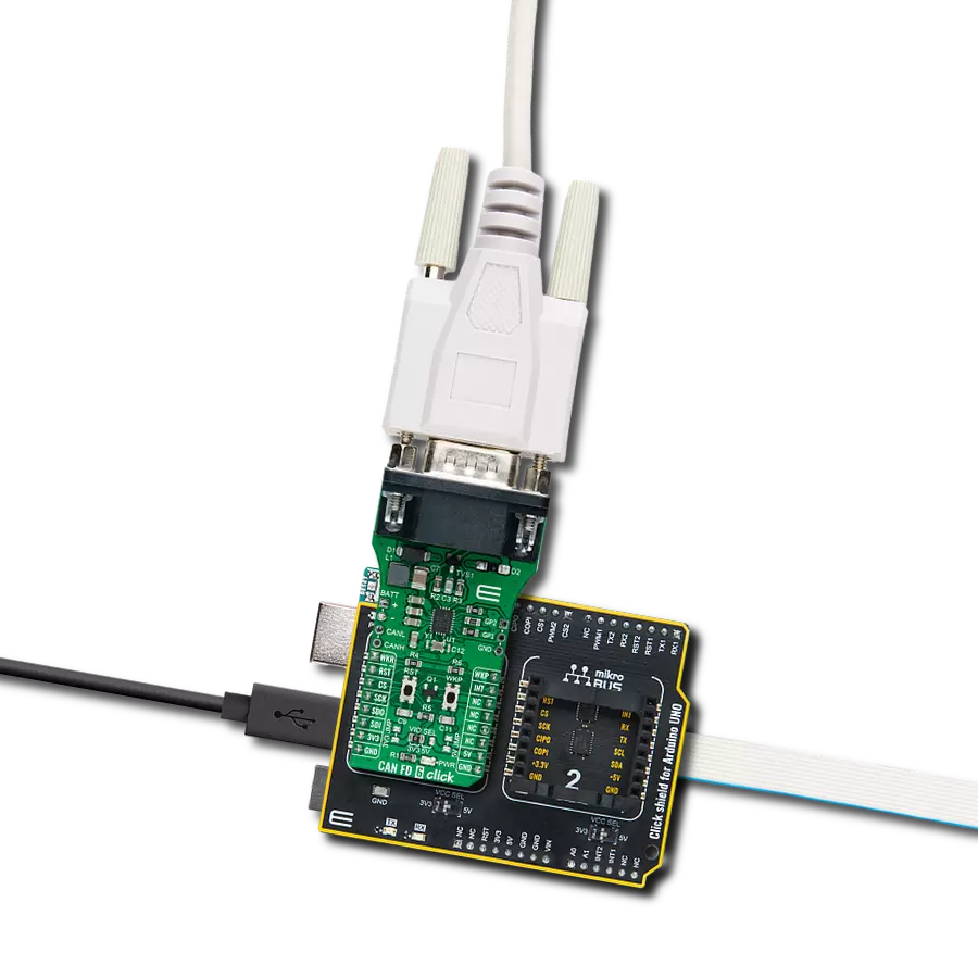
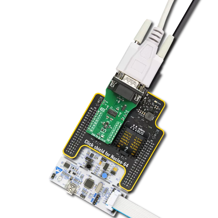
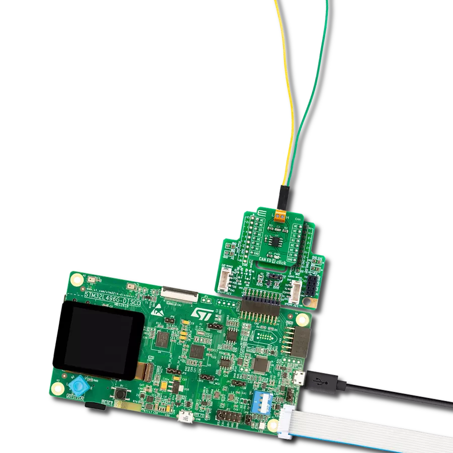
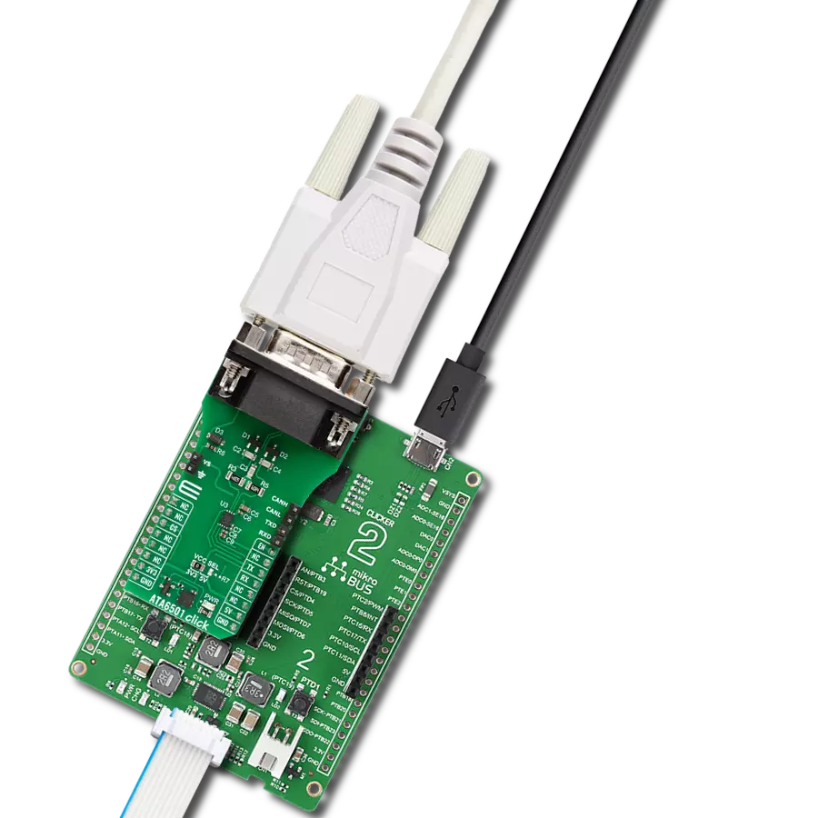
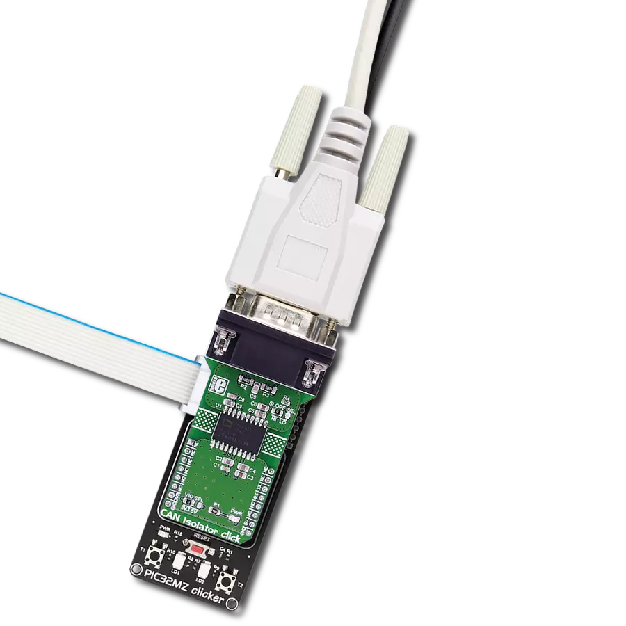
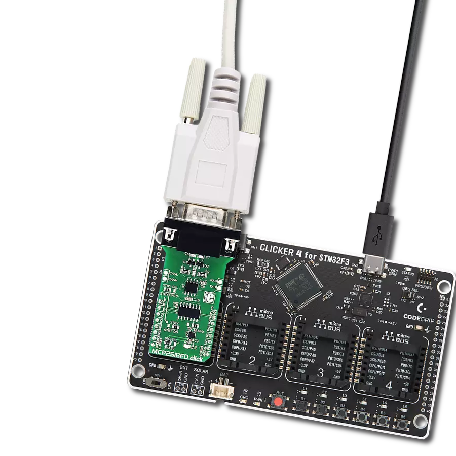
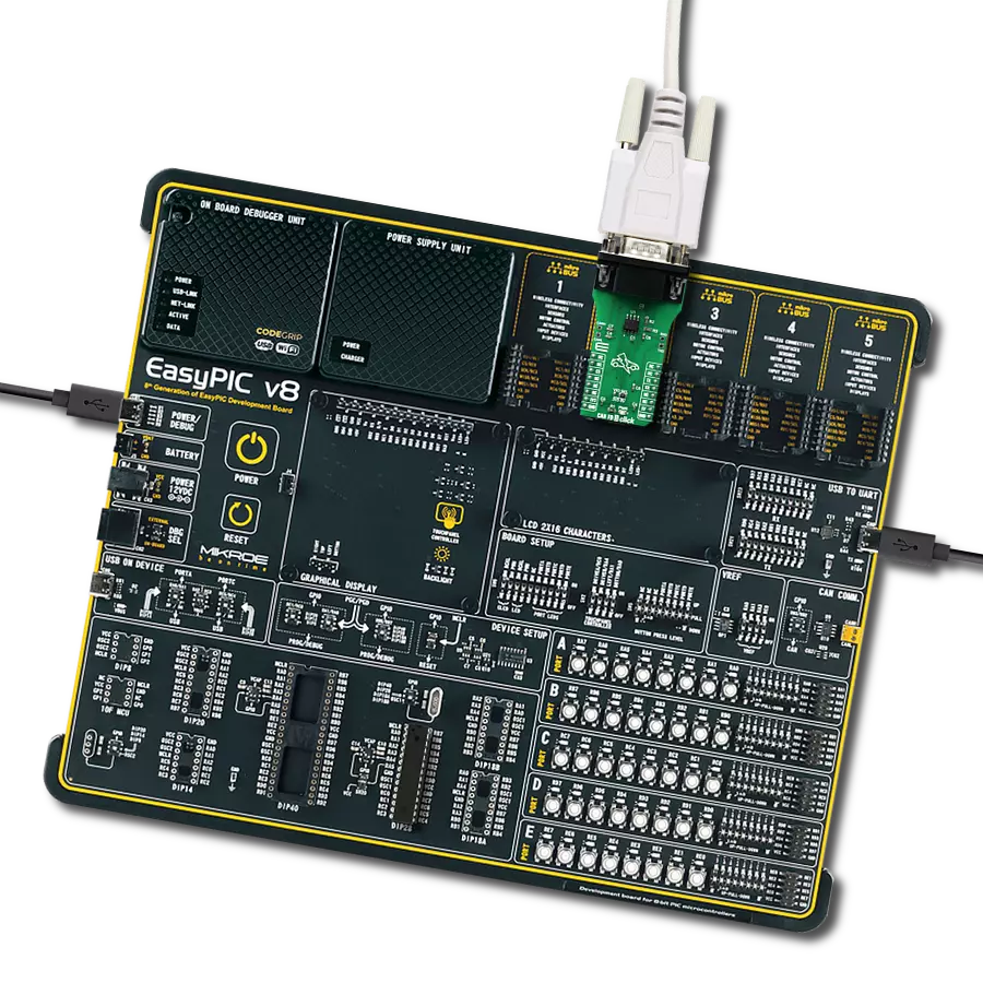
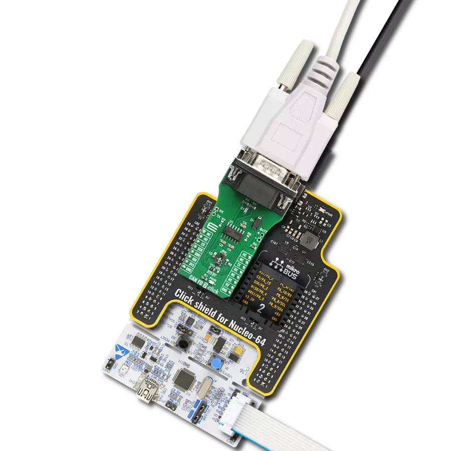
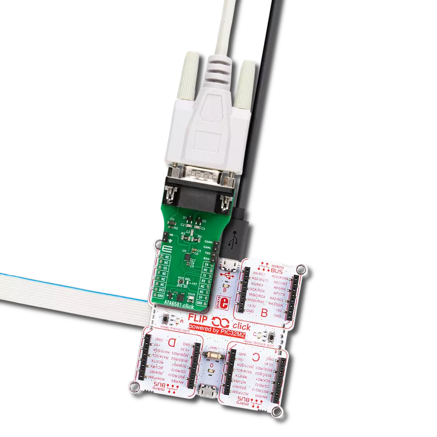
Fault-protected CAN-transceiver ideal for industrial network applications that require overvoltage protection
A
A
Hardware Overview
How does it work?
CAN Bus Click is based on the MAX13054, ±80V fault-protected CAN transceiver ideal for industrial network applications from Analog Devices. The MAX13054 links the CAN protocol controller and the physical wires of the bus lines in a control area network (CAN). These devices can be used for DeviceNet applications, requiring data rates up to 1Mbps. Its input common-mode range is greater than ±12V, exceeding the ISO11898 specification of -2V to +7V, and features ±8kV Contact Discharge protection, making these devices ideal for harsh industrial environments. Its dominant timeout feature prevents the bus from being blocked by MCU. If the TXD input is held low for greater than 1ms, the transmitter becomes disabled, driving the bus line to a recessive state. In Standby mode, when the STB pin routed on the AN and INT pin of the mikroBUS™ socket is set to a high logic state,
the transmitter is switched off, and the receiver is switched to a low-current/low-speed state. Standby mode is activated by setting the onboard SMD jumper labeled STBY SEL to an appropriate position marked as STB or GND. The MAX13054 communicates with MCU using the UART interface with the default baud rate of 115200 bps for data transfer. In addition to UART communication pins from the mikroBUS™ socket, the user can connect the TX/RX signals directly through the UART External header on the right edge of the board. This Click board™ comes equipped with the standard DB-9 connector, making interfacing with the CAN bus simple and easy. Besides, the user can connect the CAN signals directly through the CAN External header on the board's left edge. The external power supply from 2.7V to 16.5V, next to the D-9
connector, can also be brought to the header labeled BATT on the board's left side. Through SMD jumpers labeled as 3V3 JMP and 5V JMP, the MAX1658/59 from Analog Devices LDOs output voltages can power up the mikroBUS™ power rails. This feature makes the MAX13054 ideal for many applications, including automotive ones. However, it should be noted that Mikroe does not advise powering up their systems this way. That is why these jumpers are left unpopulated by default. This Click board™ can operate with either 3.3V or 5V logic voltage levels selected via the VIO SEL jumper. This way, both 3.3V and 5V capable MCUs can use the communication lines properly. Also, this Click board™ comes equipped with a library containing easy-to-use functions and an example code that can be used, as a reference, for further development.
Features overview
Development board
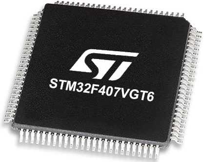
Clicker 2 for STM32 is a compact starter development board that brings the flexibility of add-on Click boards™ to your favorite microcontroller, making it a perfect starter kit for implementing your ideas. It comes with an onboard 32-bit ARM Cortex-M4 microcontroller, the STM32F407VGT6 from STMicroelectronics, two mikroBUS™ sockets for Click board™ connectivity, a USB connector, LED indicators, buttons, a JTAG programmer connector, and two 26-pin headers for interfacing with external electronics. Its compact design with clear and easily recognizable silkscreen markings allows you to build gadgets with unique functionalities and features quickly. Each part of the Clicker 2 for
STM32 development kit contains the components necessary for the most efficient operation of the same board. In addition to the possibility of choosing the Clicker 2 for STM32 programming method, using a USB HID mikroBootloader, an external mikroProg connector for STM32 programmer, or through an external ST-LINK V2 programmer, the Clicker 2 board also includes a clean and regulated power supply module for the development kit. It provides two ways of board-powering; through the USB Mini-B cable, where onboard voltage regulators provide the appropriate voltage levels to each component on the board or using a Li-Polymer battery via an onboard battery
connector. All communication methods that mikroBUS™ itself supports are on this board, including the well-established mikroBUS™ socket, reset button, and several user-configurable buttons and LED indicators. Clicker 2 for STM32 is an integral part of the Mikroe ecosystem, allowing you to create a new application in minutes. Natively supported by Mikroe software tools, it covers many aspects of prototyping thanks to a considerable number of different Click boards™ (over a thousand boards), the number of which is growing every day.
Microcontroller Overview
MCU Card / MCU
Architecture
ARM Cortex-M4
MCU Memory (KB)
10
Silicon Vendor
STMicroelectronics
Pin count
100
RAM (Bytes)
100
You complete me!
Accessories
DB9 Cable Female-to-Female (2m) cable is essential for establishing dependable serial data connections between devices. With its DB9 female connectors on both ends, this cable enables a seamless link between various equipment, such as computers, routers, switches, and other serial devices. Measuring 2 meters in length, it offers flexibility in arranging your setup without compromising data transmission quality. Crafted with precision, this cable ensures consistent and reliable data exchange, making it suitable for industrial applications, office environments, and home setups. Whether configuring networking equipment, accessing console ports, or utilizing serial peripherals, this cable's durable construction and robust connectors guarantee a stable connection. Simplify your data communication needs with the 2m DB9 female-to-female cable, an efficient solution designed to meet your serial connectivity requirements easily and efficiently.
Used MCU Pins
mikroBUS™ mapper
Take a closer look
Click board™ Schematic

Step by step
Project assembly
Software Support
Library Description
This library contains API for CAN Bus Click driver.
Key functions:
canbus_send_data- CAN Bus send data functioncanbus_set_high_speed_mode- CAN Bus high speed mode functioncanbus_set_low_current_standby_mode- CAN Bus low current standby mode function
Open Source
Code example
The complete application code and a ready-to-use project are available through the NECTO Studio Package Manager for direct installation in the NECTO Studio. The application code can also be found on the MIKROE GitHub account.
/*!
 * @file main.c
 * @brief CAN Bus Click Example.
 *
 * # Description
 * This library contains API for CAN Bus Click board™.
 * This example transmits/receives and processes data from CAN Bus Click.
 * The library initializes and defines the
 * UART bus drivers to transmit or receive data.
 *
 * The demo application is composed of two sections :
 *
 * ## Application Init
 * Initializes driver, wake-up module, and set high-speed operation mode.
 *
 * ## Application Task
 * Transmitter/Receiver task depends on uncommented code.
 * Receiver logging each received byte to the UART for data logging,
 * while transmitted send messages every 2 seconds.
 *
 * ## Additional Function
 * - static void canbus_clear_app_buf ( void ) - Function clears memory of app_buf.
 * - static err_t canbus_process ( void ) - The general process of collecting presponce
 *   that a module sends.
 *
 * @author Nenad Filipovic
 *
 */

#include "board.h"
#include "log.h"
#include "canbus.h"

#define PROCESS_BUFFER_SIZE 200

// #define TRANSMIT
#define RECIEVER

static canbus_t canbus;
static log_t logger;

static char app_buf[ PROCESS_BUFFER_SIZE ] = { 0 };
static int32_t app_buf_len = 0;
static int32_t app_buf_cnt = 0;
unsigned char demo_message[ 9 ] = { 'M', 'i', 'k', 'r', 'o', 'E', 13, 10, 0 };

/**
 * @brief CAN Bus clearing application buffer.
 * @details This function clears memory of application buffer and reset it's length and counter.
 * @note None.
 */
static void canbus_clear_app_buf ( void );

/**
 * @brief CAN Bus data reading function.
 * @details This function reads data from device and concatenates data to application buffer.
 *
 * @return @li @c  0 - Read some data.
 *         @li @c -1 - Nothing is read.
 *         @li @c -2 - Application buffer overflow.
 *
 * See #err_t definition for detailed explanation.
 * @note None.
 */
static err_t canbus_process ( void );

void application_init ( void ) {
    log_cfg_t log_cfg;        /**< Logger config object. */
    canbus_cfg_t canbus_cfg;  /**< Click config object. */

    /**
     * Logger initialization.
     * Default baud rate: 115200
     * Default log level: LOG_LEVEL_DEBUG
     * @note If USB_UART_RX and USB_UART_TX
     * are defined as HAL_PIN_NC, you will
     * need to define them manually for log to work.
     * See @b LOG_MAP_USB_UART macro definition for detailed explanation.
     */
    LOG_MAP_USB_UART( log_cfg );
    log_init( &logger, &log_cfg );
    log_info( &logger, " Application Init " );

    // Click initialization.

    canbus_cfg_setup( &canbus_cfg );
    CANBUS_MAP_MIKROBUS( canbus_cfg, MIKROBUS_1 );
    err_t init_flag  = canbus_init( &canbus, &canbus_cfg );
    if ( init_flag == UART_ERROR ) {
        log_error( &logger, " Application Init Error. " );
        log_info( &logger, " Please, run program again... " );

        for ( ; ; );
    }

    canbus_default_cfg ( &canbus );
    app_buf_len = 0;
    app_buf_cnt = 0;
    log_info( &logger, " Application Task " );
    Delay_ms ( 100 );

    canbus_set_high_speed_mode( &canbus );
    Delay_ms ( 100 );

    #ifdef TRANSMIT

        log_printf( &logger, "    Send data:    \r\n" );
        log_printf( &logger, "      MikroE      \r\n" );
        log_printf( &logger, "------------------\r\n" );
        log_printf( &logger, "  Transmit data   \r\n" );
        Delay_ms ( 1000 );

    #endif

    #ifdef RECIEVER

        log_printf( &logger, "   Receive data  \r\n" );
        Delay_ms ( 1000 );
        Delay_ms ( 1000 );

    #endif

    log_printf( &logger, "------------------\r\n" );
}

void application_task ( void ) {
   #ifdef TRANSMIT

        canbus_send_data( &canbus, demo_message );
        log_printf( &logger, "\t%s", demo_message );
        Delay_ms ( 1000 );
        Delay_ms ( 1000 );
        log_printf( &logger, "------------------\r\n" );

    #endif

    #ifdef RECIEVER

        canbus_process( );

        if ( app_buf_len > 0 ) {
            log_printf( &logger, "%s", app_buf );
            canbus_clear_app_buf(  );
        }

    #endif
}

int main ( void )
{
    /* Do not remove this line or clock might not be set correctly. */
    #ifdef PREINIT_SUPPORTED
    preinit();
    #endif

    application_init( );

    for ( ; ; )
    {
        application_task( );
    }

    return 0;
}

static void canbus_clear_app_buf ( void ) {
    memset( app_buf, 0, app_buf_len );
    app_buf_len = 0;
    app_buf_cnt = 0;
}

static err_t canbus_process ( void ) {
    int32_t rx_size;
    char rx_buff[ PROCESS_BUFFER_SIZE ] = { 0 };

    rx_size = canbus_generic_read( &canbus, rx_buff, PROCESS_BUFFER_SIZE );

    if ( rx_size > 0 ) {
        int32_t buf_cnt = 0;

        if ( app_buf_len + rx_size >= PROCESS_BUFFER_SIZE ) {
            canbus_clear_app_buf( );
            return CANBUS_ERROR;
        } else {
            buf_cnt = app_buf_len;
            app_buf_len += rx_size;
        }

        for ( int32_t rx_cnt = 0; rx_cnt < rx_size; rx_cnt++ ) {
            if ( rx_buff[ rx_cnt ] != 0 ) {
                app_buf[ ( buf_cnt + rx_cnt ) ] = rx_buff[ rx_cnt ];
            } else {
                app_buf_len--;
                buf_cnt--;
            }

        }
        return CANBUS_OK;
    }
    return CANBUS_ERROR;
}

// ------------------------------------------------------------------------ END
Additional Support
Resources
Category:CAN


