Experience instant comfort and get instant temperature results with ADT7422 and MK64FN1M0VDC12
The gold standard in temperature sensing

Published Nov 11, 2023
Click board™
Surface temp 2 Click
Dev. board
Clicker 2 for Kinetis
Compiler
NECTO Studio
MCU
MK64FN1M0VDC12
Experience the perfect blend of precision and performance with our temperature sensing solution, crafted to ASTM E1112 clinical thermometry standards.
A
A
Hardware Overview
How does it work?
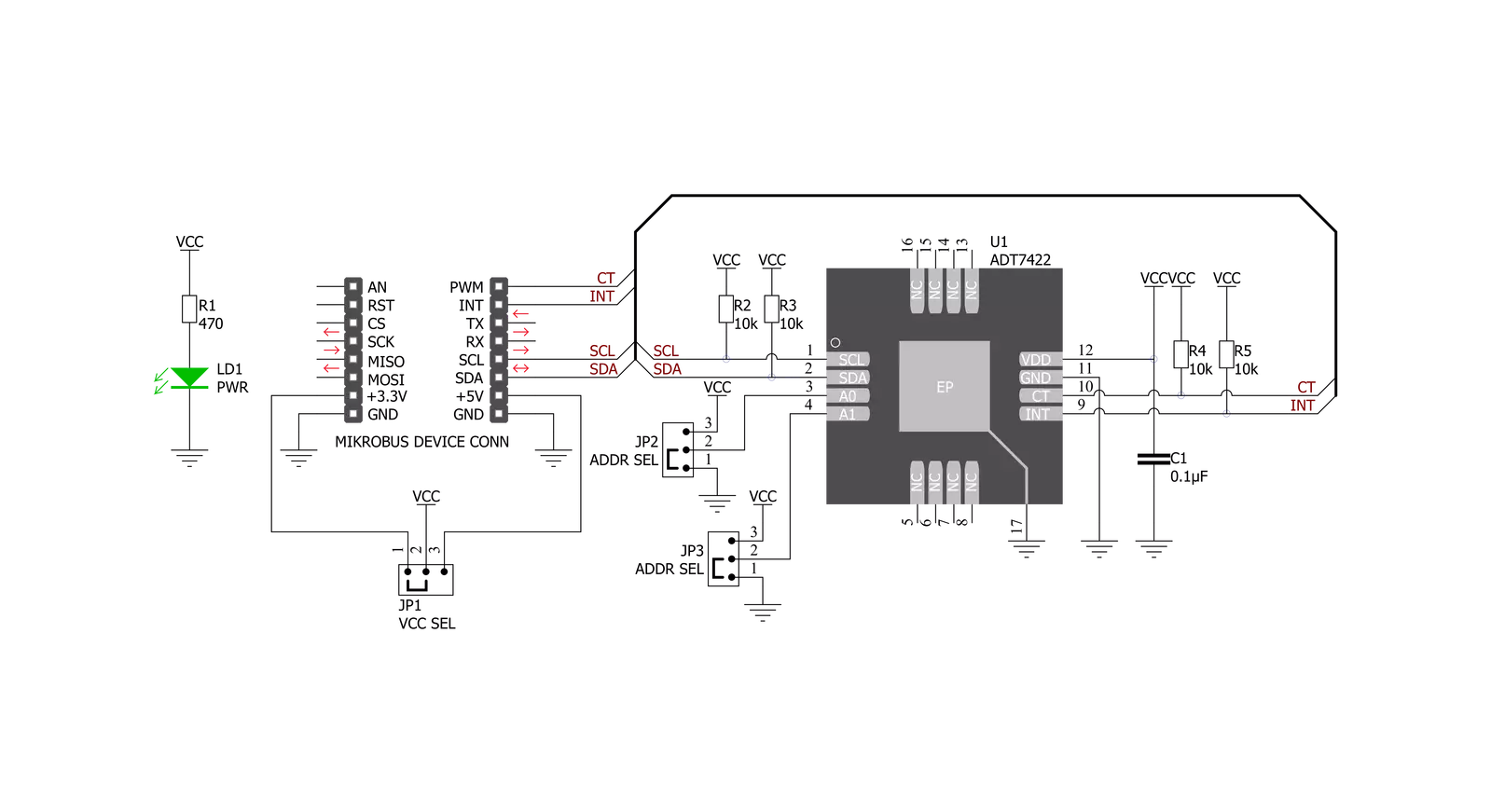
Surface temp 2 Click is based on the ADT7422, a high-accuracy 16-bit digital temperature sensor with a programmable interrupt and critical temperature indicator from Analog Devices. The ADT7422 has high accuracy and linearity over the entire rated temperature range without needing correction or calibration by the user. Operating at 3.3V, the average supply current is typically 210 μA. The ADT7420 has a shutdown mode that powers down the device and offers a shutdown current of typically 2.0 μA at 3.3 V. The ADT7422 Digital Temperature Sensor is designed to meet the ASTM E1112 standard of clinical thermometry specification. This sensor is used in applications such as Vital Signs Monitoring (VSM), medical equipment, thermocouple cold junction compensation, and laser diode temperature control. This Click board™ has a sensing pad, which is thermally connected to an ADT7422 for temperature sensing. It uses a 16-bit ADC to
monitor and digitize the temperature to 0.0078°C of resolution. The ADC resolution, by default, is set to 13 bits (0.0625°C). An internal temperature sensor generates a voltage proportional to absolute temperature, which is compared to an internal voltage reference and input into a precision digital modulator. A Σ-Δ modulator digitizes the sensor output, the charge balance type ADC. This type of converter utilizes time-domain oversampling and a high-accuracy comparator to deliver 16 bits of resolution. Surface temp 2 Click communicates with MCU using the standard I2C 2-Wire interface with a maximum frequency of 400kHz. The ADT7422 has a 7-bit slave address with the first five MSBs fixed to 10010. The address pins A0 and A1 are programmed by the user and determine the value of the last two LSBs of the slave address, which can be selected by onboard SMD jumpers labeled as ADDR SEL, allowing selection of the slave
address LSBs. It also generates a programmable interrupt signal (over/under temperature indicator) routed on the INT pin and critical overtemperature indicator CT routed on the PWM pin of the mikroBUS™ socket. Those pins have two over/under temperature modes: Comparator and Interrupt mode. The Interrupt mode is the default overtemperature mode, which sets the INT pin high when the temperature exceeds the internally defined limit value, while in Comparator mode, the INT pin returns to an inactive state when the temperature drops below that limit value. The CT pin is activated if a critical overtemperature event occurs. This Click board™ can be operated only with a 3.3V logic voltage level. The board must perform appropriate logic voltage level conversion before using MCUs with different logic levels. Also, it comes equipped with a library containing functions and an example code that can be used as a reference for further development.

Features overview
Development board
Clicker 2 for Kinetis is a compact starter development board that brings the flexibility of add-on Click boards™ to your favorite microcontroller, making it a perfect starter kit for implementing your ideas. It comes with an onboard 32-bit ARM Cortex-M4F microcontroller, the MK64FN1M0VDC12 from NXP Semiconductors, two mikroBUS™ sockets for Click board™ connectivity, a USB connector, LED indicators, buttons, a JTAG programmer connector, and two 26-pin headers for interfacing with external electronics. Its compact design with clear and easily recognizable silkscreen markings allows you to build gadgets with unique functionalities and
features quickly. Each part of the Clicker 2 for Kinetis development kit contains the components necessary for the most efficient operation of the same board. In addition to the possibility of choosing the Clicker 2 for Kinetis programming method, using a USB HID mikroBootloader or an external mikroProg connector for Kinetis programmer, the Clicker 2 board also includes a clean and regulated power supply module for the development kit. It provides two ways of board-powering; through the USB Micro-B cable, where onboard voltage regulators provide the appropriate voltage levels to each component on the board, or
using a Li-Polymer battery via an onboard battery connector. All communication methods that mikroBUS™ itself supports are on this board, including the well-established mikroBUS™ socket, reset button, and several user-configurable buttons and LED indicators. Clicker 2 for Kinetis is an integral part of the Mikroe ecosystem, allowing you to create a new application in minutes. Natively supported by Mikroe software tools, it covers many aspects of prototyping thanks to a considerable number of different Click boards™ (over a thousand boards), the number of which is growing every day.

Microcontroller Overview
MCU Card / MCU

Architecture
ARM Cortex-M4
MCU Memory (KB)
1024
Silicon Vendor
NXP
Pin count
121
RAM (Bytes)
262144
Used MCU Pins
mikroBUS™ mapper
Take a closer look
Click board™ Schematic
Step by step
Project assembly

Start by selecting your development board and Click board™. Begin with the Clicker 2 for Kinetis as your development board.


Track your results in real time
Application Output
1. Application Output - In Debug mode, the 'Application Output' window enables real-time data monitoring, offering direct insight into execution results. Ensure proper data display by configuring the environment correctly using the provided tutorial.

2. UART Terminal - Use the UART Terminal to monitor data transmission via a USB to UART converter, allowing direct communication between the Click board™ and your development system. Configure the baud rate and other serial settings according to your project's requirements to ensure proper functionality. For step-by-step setup instructions, refer to the provided tutorial.

3. Plot Output - The Plot feature offers a powerful way to visualize real-time sensor data, enabling trend analysis, debugging, and comparison of multiple data points. To set it up correctly, follow the provided tutorial, which includes a step-by-step example of using the Plot feature to display Click board™ readings. To use the Plot feature in your code, use the function: plot(*insert_graph_name*, variable_name);. This is a general format, and it is up to the user to replace 'insert_graph_name' with the actual graph name and 'variable_name' with the parameter to be displayed.

Software Support
Library Description
This library contains API for Surface temp 2 Click driver.
Key functions:
surfacetemp2_get_temperature- Get Temperature functionsurfacetemp2_set_crit_trsh- Set Critical Temperature Threshold functionsurfacetemp2_get_ct_pin- Get CT pin state function
Open Source
Code example
The complete application code and a ready-to-use project are available through the NECTO Studio Package Manager for direct installation in the NECTO Studio. The application code can also be found on the MIKROE GitHub account.
/*!
 * \file
 * \brief SurfaceTemp2 Click example
 *
 * # Description
 * This example demonstrates the use of Surface Temp 2 Click.
 *
 * The demo application is composed of two sections :
 *
 * ## Application Init
 * Initalizes the driver and configures the Click board.
 *
 * ## Application Task
 * Reads the temperature in Celsius and displays the value on the USB UART each second.
 *
 * \author MikroE Team
 *
 */
// ------------------------------------------------------------------- INCLUDES

#include "board.h"
#include "log.h"
#include "surfacetemp2.h"

// ------------------------------------------------------------------ VARIABLES

static surfacetemp2_t surfacetemp2;
static log_t logger;

uint8_t setup_val;
float temperature;

// ------------------------------------------------------ APPLICATION FUNCTIONS

void application_init ( void )
{
    log_cfg_t log_cfg;
    surfacetemp2_cfg_t cfg;

    /**
     * Logger initialization.
     * Default baud rate: 115200
     * Default log level: LOG_LEVEL_DEBUG
     * @note If USB_UART_RX and USB_UART_TX
     * are defined as HAL_PIN_NC, you will
     * need to define them manually for log to work.
     * See @b LOG_MAP_USB_UART macro definition for detailed explanation.
     */
    LOG_MAP_USB_UART( log_cfg );
    log_init( &logger, &log_cfg );
    log_info( &logger, "---- Application Init ----" );

    //  Click initialization.

    surfacetemp2_cfg_setup( &cfg );
    SURFACETEMP2_MAP_MIKROBUS( cfg, MIKROBUS_1 );
    surfacetemp2_init( &surfacetemp2, &cfg );

    setup_val = SURFACETEMP2_CFG_FLT_Q_4 | SURFACETEMP2_CFG_CT_MODE | SURFACETEMP2_CFG_RES_16;
    surfacetemp2_setup ( &surfacetemp2, setup_val );
    surfacetemp2_set_high_trsh( &surfacetemp2, 40.00 );
    surfacetemp2_set_low_trsh( &surfacetemp2, 10.00 );
    surfacetemp2_set_crit_trsh( &surfacetemp2, 70.00 );
    surfacetemp2_set_hys_val( &surfacetemp2, 5 );
    log_info( &logger, "---- Application Task ----" );
    Delay_ms ( 1000 );
}

void application_task ( void )
{
    temperature = surfacetemp2_get_temperature( &surfacetemp2 );
    log_printf( &logger, " Temperature : %.2f C \r\n", temperature );
    Delay_ms ( 1000 );
}

int main ( void )
{
    /* Do not remove this line or clock might not be set correctly. */
    #ifdef PREINIT_SUPPORTED
    preinit();
    #endif

    application_init( );

    for ( ; ; )
    {
        application_task( );
    }

    return 0;
}

// ------------------------------------------------------------------------ END


