Balance barometric pressure with MK64FN1M0VDC12
Under pressure, we thrive!

Published Oct 12, 2023
Click board™
Pressure 4 Click
Dev. board
Clicker 2 for Kinetis
Compiler
NECTO Studio
MCU
MK64FN1M0VDC12
Trust in our digital barometric sensor to keep you informed, whether you're an outdoor enthusiast, researcher, or IoT developer, enabling data-driven decisions and insights
A
A
Hardware Overview
How does it work?
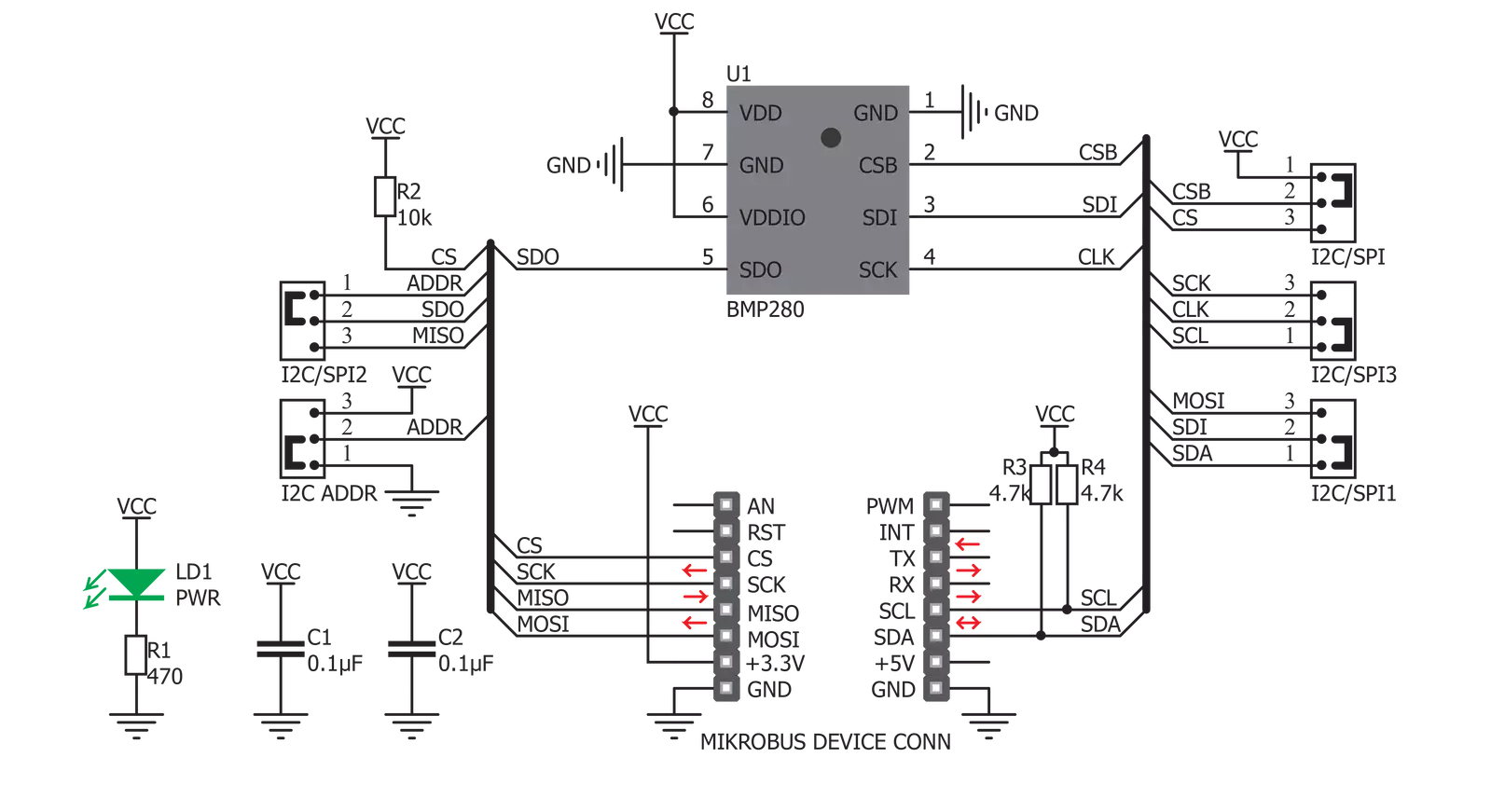
Pressure 4 Click is based on the BMP280, a digital pressure sensor from Bosch Sensortec. This sensor is produced using the Bosch proprietary APSM manufacturing technology. APSM is an abbreviation for the Advanced Porous Silicon Membrane, which is CMOS compatible technology, used to hermetically seal the sensor cavity, in an all-silicon process. This advanced MEMS technology offers a high measurement precision of only 0.12 hPa, as well as low TOC (thermal coefficient) of only 1.5 Pa/K. The sensor is enclosed in a small metal lid housing and is very resilient: it can operate in a range of 300 hPa to 1100 hPa but can withstand up to 20,000 hPa before the membrane breaks down. The BMP280 offers a set of pressure and temperature measurement options. It can be programmed to skip either thermal or pressure measurement, allowing faster measurement of the required property. The low TOC of only 1.5K/Pa allows reading of the pressure with very small drift over temperature. Resolution of 0.12 hPa allows calculating of the altitude with the accuracy of 1m, which is ideal for indoor navigation applications (drones, flying toy models, and similar). Since this device is aimed at low power applications, it is
powered by the mikroBUS™ 3.3V rail and does not allow voltages up to 5V. Therefore the Click board™ supports only 3.3V MCUs and it is not intended to be connected or controlled via the 5V MCU without a proper level shifting circuitry. This sensor is comprised of a mixed signal front end (ASIC) and the piezo-sensitive pressure sensing element. The ASIC section provides analog to digital conversion of the measurement as well as the signal processing, in the form of the IIR filtering. The measurement readings and the compensation parameters are available at I2C or SPI bus pins of the BMP280 routed to the mikroBUS™ standard SPI and I2C pins. Pressure 4 click offers a selection between the two, by switching SMD jumpers labeled as I2C SPI to an appropriate position. Note that all the jumpers have to be placed to the same side, as mixed SPI and I2C positions will render the Click board™ unresponsive. Additionally, selection of the I2C communication protocol allows the least significant bit (LSB) of the I2C slave address of the device to be set. This can be done with the SMD jumper, labeled as I2C ADDR. The overall power consumption depends on several factors, such as the oversampling value, measurement rate, power
mode, standby duration, and so on. Bosch Sensortec recommends a set of operational parameters for different applications, in a form of a table, in the BMP280 datasheet. In general, this sensor allows several power modes, regardless of the selected measurement parameters, such as Sleep, Forced, and Normal mode. When the measurement is completed, the raw ADC values will be available in the output registers. However, to obtain actual pressure and temperature readings, a compensation algorithm needs to be applied to these raw values. A set of compensation parameters is available in the non-volatile memory of each sensor device. These compensation parameters take into account slight differences between the produced sensors and each BMP280 sensor device has its own set of compensation parameters. The BMP280 datasheet offers detailed instructions on how to apply these compensating algorithms properly. However, MikroElektronika provides a library that contains functions, which can be used for the simplified operation of the Pressure 4 click. The library also contains an example application, which demonstrates their use. This example application can be used as a reference for custom designs.


Features overview
Development board
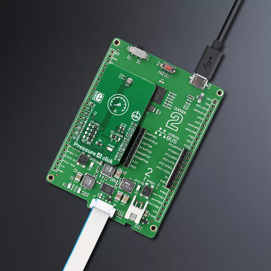
Clicker 2 for Kinetis is a compact starter development board that brings the flexibility of add-on Click boards™ to your favorite microcontroller, making it a perfect starter kit for implementing your ideas. It comes with an onboard 32-bit ARM Cortex-M4F microcontroller, the MK64FN1M0VDC12 from NXP Semiconductors, two mikroBUS™ sockets for Click board™ connectivity, a USB connector, LED indicators, buttons, a JTAG programmer connector, and two 26-pin headers for interfacing with external electronics. Its compact design with clear and easily recognizable silkscreen markings allows you to build gadgets with unique functionalities and
features quickly. Each part of the Clicker 2 for Kinetis development kit contains the components necessary for the most efficient operation of the same board. In addition to the possibility of choosing the Clicker 2 for Kinetis programming method, using a USB HID mikroBootloader or an external mikroProg connector for Kinetis programmer, the Clicker 2 board also includes a clean and regulated power supply module for the development kit. It provides two ways of board-powering; through the USB Micro-B cable, where onboard voltage regulators provide the appropriate voltage levels to each component on the board, or
using a Li-Polymer battery via an onboard battery connector. All communication methods that mikroBUS™ itself supports are on this board, including the well-established mikroBUS™ socket, reset button, and several user-configurable buttons and LED indicators. Clicker 2 for Kinetis is an integral part of the Mikroe ecosystem, allowing you to create a new application in minutes. Natively supported by Mikroe software tools, it covers many aspects of prototyping thanks to a considerable number of different Click boards™ (over a thousand boards), the number of which is growing every day.

Microcontroller Overview
MCU Card / MCU

Architecture
ARM Cortex-M4
MCU Memory (KB)
1024
Silicon Vendor
NXP
Pin count
121
RAM (Bytes)
262144
Used MCU Pins
mikroBUS™ mapper
Take a closer look
Click board™ Schematic
Step by step
Project assembly

Start by selecting your development board and Click board™. Begin with the Clicker 2 for Kinetis as your development board.


Software Support
Library Description
This library contains API for Pressure 4 Click driver.
Key functions:
pressure4_read_id- This function returns the contents of the chipid registerpressure4_get_temperature- This function returning the calculated temperature valuepressure4_get_pressure- This function returning the calculated value of the pressure
Open Source
Code example
The complete application code and a ready-to-use project are available through the NECTO Studio Package Manager for direct installation in the NECTO Studio. The application code can also be found on the MIKROE GitHub account.
/*!
 * \file
 * \brief Pressure4 Click example
 *
 * # Description
 * This app measure barometric pressure.
 *
 * The demo application is composed of two sections :
 *
 * ## Application Init
 * Initializes the Click board.
 *
 * ## Application Task
 * The pressure and temperature data is read from the sensor
 * and it is printed to the UART.
 *
 * \author MikroE Team
 *
 */
// ------------------------------------------------------------------- INCLUDES

#include "board.h"
#include "log.h"
#include "pressure4.h"

// ------------------------------------------------------------------ VARIABLES

static pressure4_t pressure4;
static log_t logger;

// ------------------------------------------------------ APPLICATION FUNCTIONS

void application_init ( void )
{
    log_cfg_t log_cfg;
    pressure4_cfg_t cfg;

    /**
     * Logger initialization.
     * Default baud rate: 115200
     * Default log level: LOG_LEVEL_DEBUG
     * @note If USB_UART_RX and USB_UART_TX
     * are defined as HAL_PIN_NC, you will
     * need to define them manually for log to work.
     * See @b LOG_MAP_USB_UART macro definition for detailed explanation.
     */
    LOG_MAP_USB_UART( log_cfg );
    log_init( &logger, &log_cfg );
    log_info( &logger, " Application Init " );

    //  Click initialization.
    pressure4_cfg_setup( &cfg );
    PRESSURE4_MAP_MIKROBUS( cfg, MIKROBUS_1 );
    pressure4_init( &pressure4, &cfg );

    pressure4_default_cfg( &pressure4 );
    log_info( &logger, " Application Task " );
}

void application_task ( void )
{
    float pressure = 0;
    float temperature = 0;

    temperature = pressure4_get_temperature( &pressure4 );
    log_printf( &logger, "Temperature : %.2f degC\r\n", temperature );
    Delay_ms ( 100 );

    pressure = pressure4_get_pressure( &pressure4 );
    log_printf( &logger, "Pressure : %.2f mBar\r\n", pressure );
    log_printf( &logger, "========================\r\n" );

    Delay_ms ( 500 );
}

int main ( void )
{
    /* Do not remove this line or clock might not be set correctly. */
    #ifdef PREINIT_SUPPORTED
    preinit();
    #endif

    application_init( );

    for ( ; ; )
    {
        application_task( );
    }

    return 0;
}

// ------------------------------------------------------------------------ END


