Deliver data and control signals where you need them most thanks to the MAX41460 and MK64FN1M0VDC12
Transmitting excellence, everywhere.

Published Nov 11, 2023
Click board™
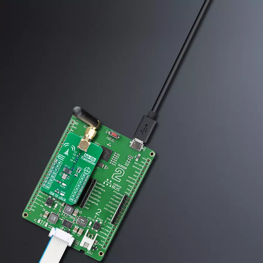
ISM TX Click
Dev. board
Clicker 2 for Kinetis
Compiler
NECTO Studio
MCU
MK64FN1M0VDC12
Our ISM RF transmitter solution ensures excellence in wireless data transmission across a spectrum of industries, from IoT to remote monitoring.
A
A
Hardware Overview
How does it work?
ISM TX Click is based on the MAX41460, a UHF sub-GHz ISM/SRD transmitter designed to transmit On-Off Keying (OOK), Amplitude- Shift Keying (ASK), Frequency-Shift Keying (FSK), and Gaussian (G)FSK (or 2GFSK) data from Analog Devices. The crystal-based architecture of the MAX41460 provides greater modulation depth, faster frequency settling, higher tolerance of the transmit frequency, and reduced temperature dependence. It integrates a fractional phase-locked loop (PLL), so a single, low-cost crystal of 16MHz used on this Click board™ can generate commonly used worldwide sub-GHz frequencies. A buffered clock-out signal makes the device compatible with almost any MCU or code-hopping generator. The MAX41460 features a fast oscillator Wake-Up upon data activity detection and has an Auto-Shutdown feature to extend battery life. This Click board™ has four major operating states: Shutdown, Stand-By, Programming, and Transmitter-Enabled Mode.
These states describe the Power-ON/Power-OFF status of the transmitter's three primary internal circuit blocks: the crystal oscillator (XO), the PLL synthesizer, and a high-efficiency, open-drain switching-mode power amplifier (PA). To ensure the MAX41460 enters the shutdown state after Power-On, the DATA pin must be held low at Power-On. The PA pin is used to adjust the frequency with only frequency-dependent components required for the external antenna-matching network that are connected so that the frequency of this Click board™ is fixed to 433.92MHz. The MAX41460 communicates with MCU using the standard SPI serial interface with a maximum frequency of 20 MHz. The device can support two types of SPI transactions: register access only and register access, followed by data transmission. In both Shutdown and Stand-By states, programming through the SPI interface is not allowed. Configuration register values are retained in all
states unless changed by programming or if the device is powered off. This Click board™, alongside the power LED indicator, has an additional green LED indicator labeled as DATA used to visually indicate the successful transmission of data across the SPI interface. ISM TX Click possesses the SMA antenna connector, and it can be used for connecting the appropriate antenna that MIKROE has in its offer, such as Rubber Antenna GSM/GPRS Right Angle. This antenna is an excellent choice for all GSM/GPRS applications and supports a range of frequencies and bands. This Click board™ can be operated only with a 3.3V logic voltage level. The board must perform appropriate logic voltage level conversion before using MCUs with different logic levels. Also, it comes equipped with a library containing functions and an example code that can be used as a reference for further development.

Features overview
Development board
Clicker 2 for Kinetis is a compact starter development board that brings the flexibility of add-on Click boards™ to your favorite microcontroller, making it a perfect starter kit for implementing your ideas. It comes with an onboard 32-bit ARM Cortex-M4F microcontroller, the MK64FN1M0VDC12 from NXP Semiconductors, two mikroBUS™ sockets for Click board™ connectivity, a USB connector, LED indicators, buttons, a JTAG programmer connector, and two 26-pin headers for interfacing with external electronics. Its compact design with clear and easily recognizable silkscreen markings allows you to build gadgets with unique functionalities and
features quickly. Each part of the Clicker 2 for Kinetis development kit contains the components necessary for the most efficient operation of the same board. In addition to the possibility of choosing the Clicker 2 for Kinetis programming method, using a USB HID mikroBootloader or an external mikroProg connector for Kinetis programmer, the Clicker 2 board also includes a clean and regulated power supply module for the development kit. It provides two ways of board-powering; through the USB Micro-B cable, where onboard voltage regulators provide the appropriate voltage levels to each component on the board, or
using a Li-Polymer battery via an onboard battery connector. All communication methods that mikroBUS™ itself supports are on this board, including the well-established mikroBUS™ socket, reset button, and several user-configurable buttons and LED indicators. Clicker 2 for Kinetis is an integral part of the Mikroe ecosystem, allowing you to create a new application in minutes. Natively supported by Mikroe software tools, it covers many aspects of prototyping thanks to a considerable number of different Click boards™ (over a thousand boards), the number of which is growing every day.

Microcontroller Overview
MCU Card / MCU

Architecture
ARM Cortex-M4
MCU Memory (KB)
1024
Silicon Vendor
NXP
Pin count
121
RAM (Bytes)
262144
You complete me!
Accessories
Right angle 433MHz rubber antenna boasts a frequency range of 433MHz, ensuring optimal performance within this spectrum. With a 50Ohm impedance, it facilitates efficient signal transmission. The antenna's vertical polarization enhances signal reception in a specific orientation. Featuring a 1.5dB gain, it can improve signal strength to some extent. The antenna can handle a maximum input power of 50W, making it suitable for various applications. Its compact 50mm length minimizes spatial requirements. Equipped with an SMA male connector, it easily interfaces with compatible devices. This antenna is an adaptable solution for wireless communication needs, particularly when vertical polarization is crucial.

868MHz right-angle rubber antenna is a compact and versatile solution for wireless communication. Operating within the frequency range of 868-915MHz, it ensures optimal signal reception and transmission. With a 50-ohm impedance, it's compatible with various devices and systems. This antenna boasts a 2dB gain, enhancing signal strength and extending communication range. Its vertical polarization further contributes to signal clarity. Designed to handle up to 50W of input power, it's a robust choice for various applications. Measuring just 48mm in length, this antenna is both discreet and practical. Its SMA male connector ensures a secure and reliable connection to your equipment. Whether you're working with IoT devices, remote sensors, or other wireless technologies, the 868MHz right-angle antenna offers the performance and flexibility you need for seamless communication.

Used MCU Pins
mikroBUS™ mapper
Take a closer look
Click board™ Schematic

Step by step
Project assembly

Start by selecting your development board and Click board™. Begin with the Clicker 2 for Kinetis as your development board.


Track your results in real time
Application Output
1. Application Output - In Debug mode, the 'Application Output' window enables real-time data monitoring, offering direct insight into execution results. Ensure proper data display by configuring the environment correctly using the provided tutorial.

2. UART Terminal - Use the UART Terminal to monitor data transmission via a USB to UART converter, allowing direct communication between the Click board™ and your development system. Configure the baud rate and other serial settings according to your project's requirements to ensure proper functionality. For step-by-step setup instructions, refer to the provided tutorial.

3. Plot Output - The Plot feature offers a powerful way to visualize real-time sensor data, enabling trend analysis, debugging, and comparison of multiple data points. To set it up correctly, follow the provided tutorial, which includes a step-by-step example of using the Plot feature to display Click board™ readings. To use the Plot feature in your code, use the function: plot(*insert_graph_name*, variable_name);. This is a general format, and it is up to the user to replace 'insert_graph_name' with the actual graph name and 'variable_name' with the parameter to be displayed.

Software Support
Library Description
This library contains API for ISM TX Click driver.
Key functions:
ismtx_set_cfg- ISM TX writing configuration.ismtx_set_frequency- Setting specific frequency for transmission.ismtx_transmit_data- Function for transmitting data with preamble byte and lenght.
Open Source
Code example
The complete application code and a ready-to-use project are available through the NECTO Studio Package Manager for direct installation in the NECTO Studio. The application code can also be found on the MIKROE GitHub account.
/*!
 * @file main.c
 * @brief ISMTX Click example
 *
 * # Description
 * This application shows capability of ISM TX Click board.
 * It sets default configuration, and transmits data in
 * manchester encoding with FSK or ASK signal modulation.
 *
 * The demo application is composed of two sections :
 *
 * ## Application Init
 * Initialization of log and communication, sets signal modulation,
 * resets device, and sets default configuration for selected modulation.
 *
 * ## Application Task
 * Transmits data via external antenna in span of 100ms.
 *
 * @note
 * Default configuration configures device and sets transmission frequency to 433.92 MHz.
 * If selected modulation is FSK frequency deviation is set to 40kHz.
 *
 * @author Luka Filipovic
 *
 */

#include "board.h"
#include "log.h"
#include "ismtx.h"

#define PREAMBLE_BYTE   0xFF

uint8_t tx_data_buf[ 9 ] = { 'M', 'I', 'K', 'R', 'O', 'E', '\r', '\n', 0 };

static ismtx_t ismtx;
static log_t logger;

void application_init ( void )
{
    log_cfg_t log_cfg;      /**< Logger config object. */
    ismtx_cfg_t ismtx_cfg;  /**< Click config object. */

    /**
     * Logger initialization.
     * Default baud rate: 115200
     * Default log level: LOG_LEVEL_DEBUG
     * @note If USB_UART_RX and USB_UART_TX
     * are defined as HAL_PIN_NC, you will
     * need to define them manually for log to work.
     * See @b LOG_MAP_USB_UART macro definition for detailed explanation.
     */
    LOG_MAP_USB_UART( log_cfg );
    log_init( &logger, &log_cfg );
    log_info( &logger, " Application Init " );

    // Click initialization.
    ismtx_cfg_setup( &ismtx_cfg );
    ISMTX_MAP_MIKROBUS( ismtx_cfg, MIKROBUS_1 );
    if ( SPI_MASTER_ERROR == ismtx_init( &ismtx, &ismtx_cfg ) )
    {
        log_error( &logger, " Application Init Error. " );
        log_info( &logger, " Please, run program again... " );
        for ( ; ; );
    }

    ismtx.modulation = ISM_TX_MODULATION_FSK;

    ismtx_soft_reset( &ismtx );

    if ( ismtx_default_cfg ( &ismtx ) < 0 )
    {
        log_error( &logger, " Application Init Error. " );
        log_info( &logger, " Please, select correct signal modulation... " );
        for ( ; ; );
    }

    log_info( &logger, " Application Task " );
}

void application_task ( void )
{
    log_info( &logger, " Data sent: %s", tx_data_buf );
    ismtx_transmit_data( &ismtx, PREAMBLE_BYTE, tx_data_buf, sizeof( tx_data_buf ) );
    Delay_ms ( 100 );
}

int main ( void )
{
    /* Do not remove this line or clock might not be set correctly. */
    #ifdef PREINIT_SUPPORTED
    preinit();
    #endif

    application_init( );

    for ( ; ; )
    {
        application_task( );
    }

    return 0;
}

// ------------------------------------------------------------------------ END
Additional Support
Resources
Category:Sub-1 GHz Transceievers


