Unleash your motor's full potential with MIC4605 and MK64FN1M0VDC12
PWM motor control at its best!

Published Jul 20, 2023
Click board™
DC Motor 8 Click
Dev. board
Clicker 2 for Kinetis
Compiler
NECTO Studio
MCU
MK64FN1M0VDC12
With our PWM motor control solution, you can effortlessly regulate the speed and direction of your DC motors, enabling smooth and efficient operation
A
A
Hardware Overview
How does it work?
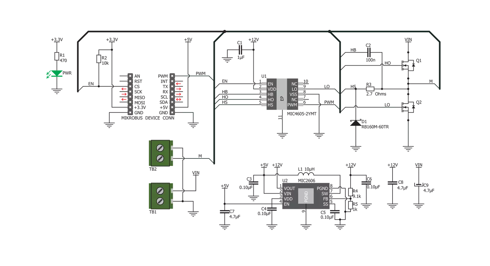
DC Motor 8 Click is based on the MIC4605, 85V half-bridge MOSFET driver with adaptive dead time and shoot-through protection from Microchip. This IC uses the input on its PWM pin to regulate the switching state of the output MOSFETs. The fact that it is 85V tolerant allows for a substantial margin against kickback voltage that appears as the result of the rotation of the motor. In practice, twice the power supply used for the motor should be considered a safe margin. This IC has more than enough to accommodate the maximum voltage allowed on its input, which is 40V. DC Motor 8 works in a half-bridge topology, which means it can only run the connected motor in one direction. However, the polarity of the connected motor can be flipped, which will change the rotational direction of the motor. The connected input voltage must not be reversed and must stay connected as labeled on the PCB. Although the maximum input voltage rating is 40V, it is a good practice never to supply the motor with the maximum allowed voltage, as it may result in overheating of the MOSFETs and other components, depending on the used motor and the mechanical load it is exposed to. The device should never be pushed to work at the maximum
allowed ratings. While the PWM input is at the HIGH logic state, the HO output pin that drives the high-side power MOSFET is active, and the circuit is closed through the high-side power MOSFET, motor coil, and the ground. When the PWM input signal goes LOW, it forces the HO output to also go low, within about 35ns. The HS pin monitors the driver state - when the HS voltage drops under 2.2V, the high side MOSFET is closed, and LO output is activated after a short delay (about 35ns of rise time). A further drop of the HS voltage causes a latch, which can only be reset by the PWM signal HIGH logic level. If the HS level fails to drop under 2.2V, the internal 250ns delay is activated, and the HS pin latches afterward. This prevents the HS ringing from causing an undetermined state of the LO output. When the PWM signal goes HIGH again, it will force the LO output to a LOW within another 35ns, after which the HO pin can start going into the HIGH level again. This mechanism ensures that no shoot-through ever occurs. Shoot-through happens when both MOSFETs are active and when the current goes right through them, from the power supply to the ground, causing dissipation, ringing, and even damage in some cases. Besides the
PWM pin routed to the mikroBUS™, the EN pin used to enable the device is also routed to the mikroBUS™ CS pin. Logic HIGH will set the device to work in normal mode, while LOW logic level will put the device into the power conservative shutdown mode. This pin is pulled HIGH with the onboard resistor. The VIN power terminal, which provides up to 40V power supply for the DC motor, is completely isolated from the driver circuitry. However, to operate correctly, the driver must provide enough voltage to activate the MOSFETs. For this purpose, DC Motor 8 click employs a boost converter made of MIC2606, a 2MHz boost regulator from Microchip. The boost regulator circuitry provides 12V out of 5V from the mikroBUS™, which allows for ideal MOSFET switching conditions, keeping the resistance through the MOSFET (RDSON) at optimal levels. VOUT terminal is used to connect a load. A small to medium-powered DC motor with two connection points and up to 40V can be used with this click board™. The voltage at the VIN terminal is used to power the motor on, while the click itself is being powered from the mikroBUS™ voltage rails. For proper operation, both 3.3V and 5V voltages must be present on the mikroBUS™.

Features overview
Development board
Clicker 2 for Kinetis is a compact starter development board that brings the flexibility of add-on Click boards™ to your favorite microcontroller, making it a perfect starter kit for implementing your ideas. It comes with an onboard 32-bit ARM Cortex-M4F microcontroller, the MK64FN1M0VDC12 from NXP Semiconductors, two mikroBUS™ sockets for Click board™ connectivity, a USB connector, LED indicators, buttons, a JTAG programmer connector, and two 26-pin headers for interfacing with external electronics. Its compact design with clear and easily recognizable silkscreen markings allows you to build gadgets with unique functionalities and
features quickly. Each part of the Clicker 2 for Kinetis development kit contains the components necessary for the most efficient operation of the same board. In addition to the possibility of choosing the Clicker 2 for Kinetis programming method, using a USB HID mikroBootloader or an external mikroProg connector for Kinetis programmer, the Clicker 2 board also includes a clean and regulated power supply module for the development kit. It provides two ways of board-powering; through the USB Micro-B cable, where onboard voltage regulators provide the appropriate voltage levels to each component on the board, or
using a Li-Polymer battery via an onboard battery connector. All communication methods that mikroBUS™ itself supports are on this board, including the well-established mikroBUS™ socket, reset button, and several user-configurable buttons and LED indicators. Clicker 2 for Kinetis is an integral part of the Mikroe ecosystem, allowing you to create a new application in minutes. Natively supported by Mikroe software tools, it covers many aspects of prototyping thanks to a considerable number of different Click boards™ (over a thousand boards), the number of which is growing every day.

Microcontroller Overview
MCU Card / MCU

Architecture
ARM Cortex-M4
MCU Memory (KB)
1024
Silicon Vendor
NXP
Pin count
121
RAM (Bytes)
262144
You complete me!
Accessories
DC Gear Motor - 430RPM (3-6V) represents an all-in-one combination of a motor and gearbox, where the addition of gear leads to a reduction of motor speed while increasing the torque output. This gear motor has a spur gearbox, making it a highly reliable solution for applications with lower torque and speed requirements. The most critical parameters for gear motors are speed, torque, and efficiency, which are, in this case, 520RPM with no load and 430RPM at maximum efficiency, alongside a current of 60mA and a torque of 50g.cm. Rated for a 3-6V operational voltage range and clockwise/counterclockwise rotation direction, this motor represents an excellent solution for many functions initially performed by brushed DC motors in robotics, medical equipment, electric door locks, and much more.

Used MCU Pins
mikroBUS™ mapper
Take a closer look
Click board™ Schematic
Step by step
Project assembly

Start by selecting your development board and Click board™. Begin with the Clicker 2 for Kinetis as your development board.


Software Support
Library Description
This library contains API for DC Motor 8 Click driver.
Key functions:
dcmotor8_set_duty_cycle- This function sets the PWM duty cycledcmotor8_pwm_start- This function starts PWM moduledcmotor8_pwm_stop- This function stops PWM module
Open Source
Code example
The complete application code and a ready-to-use project are available through the NECTO Studio Package Manager for direct installation in the NECTO Studio. The application code can also be found on the MIKROE GitHub account.
/*!
 * @file
 * @brief DcMotor8 Click example
 *
 * # Description
 * This Click can drive simple DC motors with brushes, providing them with a significant amount
 * of current and voltage up to 40V. The Click has one control input, that uses the PWM signal
 * from the host MCU. It uses the half-bridge topology to regulate the speed of the motor
 * rotation, employs advanced dead-time circuitry that monitors the output stage, providing
 * maximum switching efficiency and features an advanced technique to avoid shoot-through
 * currents.
 *
 * The demo application is composed of two sections :
 *
 * ## Application Init
 * Initializes the driver and enables the Click board.
 *
 * ## Application Task
 * This is an example that demonstrates the use of DC Motor 8 Click
 * board by increasing and decreasing the motor speed.
 * DC Motor 8 Click communicates with the register via the PWM interface.
 * Results are being sent to the Usart Terminal where you can track their changes.
 *
 * @author Nikola Peric
 *
 */
// ------------------------------------------------------------------- INCLUDES

#include "board.h"
#include "log.h"
#include "dcmotor8.h"

// ------------------------------------------------------------------ VARIABLES

static dcmotor8_t dcmotor8;
static log_t logger;

// ------------------------------------------------------ APPLICATION FUNCTIONS

void application_init ( void )
{
    log_cfg_t log_cfg;
    dcmotor8_cfg_t cfg;

    /**
     * Logger initialization.
     * Default baud rate: 115200
     * Default log level: LOG_LEVEL_DEBUG
     * @note If USB_UART_RX and USB_UART_TX
     * are defined as HAL_PIN_NC, you will
     * need to define them manually for log to work.
     * See @b LOG_MAP_USB_UART macro definition for detailed explanation.
     */
    LOG_MAP_USB_UART( log_cfg );
    log_init( &logger, &log_cfg );
    log_info( &logger, "---- Application Init ----" );

    //  Click initialization.

    dcmotor8_cfg_setup( &cfg );
    DCMOTOR8_MAP_MIKROBUS( cfg, MIKROBUS_1 );
    dcmotor8_init( &dcmotor8, &cfg );

    dcmotor8_set_duty_cycle ( &dcmotor8, 0.0 );
    dcmotor8_enable ( &dcmotor8, DCMOTOR8_ENABLE );
    dcmotor8_pwm_start( &dcmotor8 );
    log_info( &logger, "---- Application Task ----" );
    Delay_ms ( 500 );
}

void application_task ( void )
{
    static int8_t duty_cnt = 1;
    static int8_t duty_inc = 1;
    float duty = duty_cnt / 10.0;

    dcmotor8_set_duty_cycle ( &dcmotor8, duty );
    log_printf( &logger, "Duty: %d%%\r\n", ( uint16_t )( duty_cnt * 10 ) );
    Delay_ms ( 500 );

    if ( 10 == duty_cnt )
    {
        duty_inc = -1;
    }
    else if ( 0 == duty_cnt )
    {
        duty_inc = 1;
    }
    duty_cnt += duty_inc;
}

int main ( void )
{
    /* Do not remove this line or clock might not be set correctly. */
    #ifdef PREINIT_SUPPORTED
    preinit();
    #endif

    application_init( );

    for ( ; ; )
    {
        application_task( );
    }

    return 0;
}

// ------------------------------------------------------------------------ END


