Create stunning lighting effects easily using PCA9532 and MK64FN1M0VDC12
Shine brighter, smarter, with our LED driver innovation!

Published Sep 09, 2023
Click board™
LED Driver 12 Click
Dev. board
Clicker 2 for Kinetis
Compiler
NECTO Studio
MCU
MK64FN1M0VDC12
Experience the future of illumination with our LED driver solution, providing a hassle-free approach to managing multiple LEDs, ensuring your lights shine as brilliantly as your imagination
A
A
Hardware Overview
How does it work?
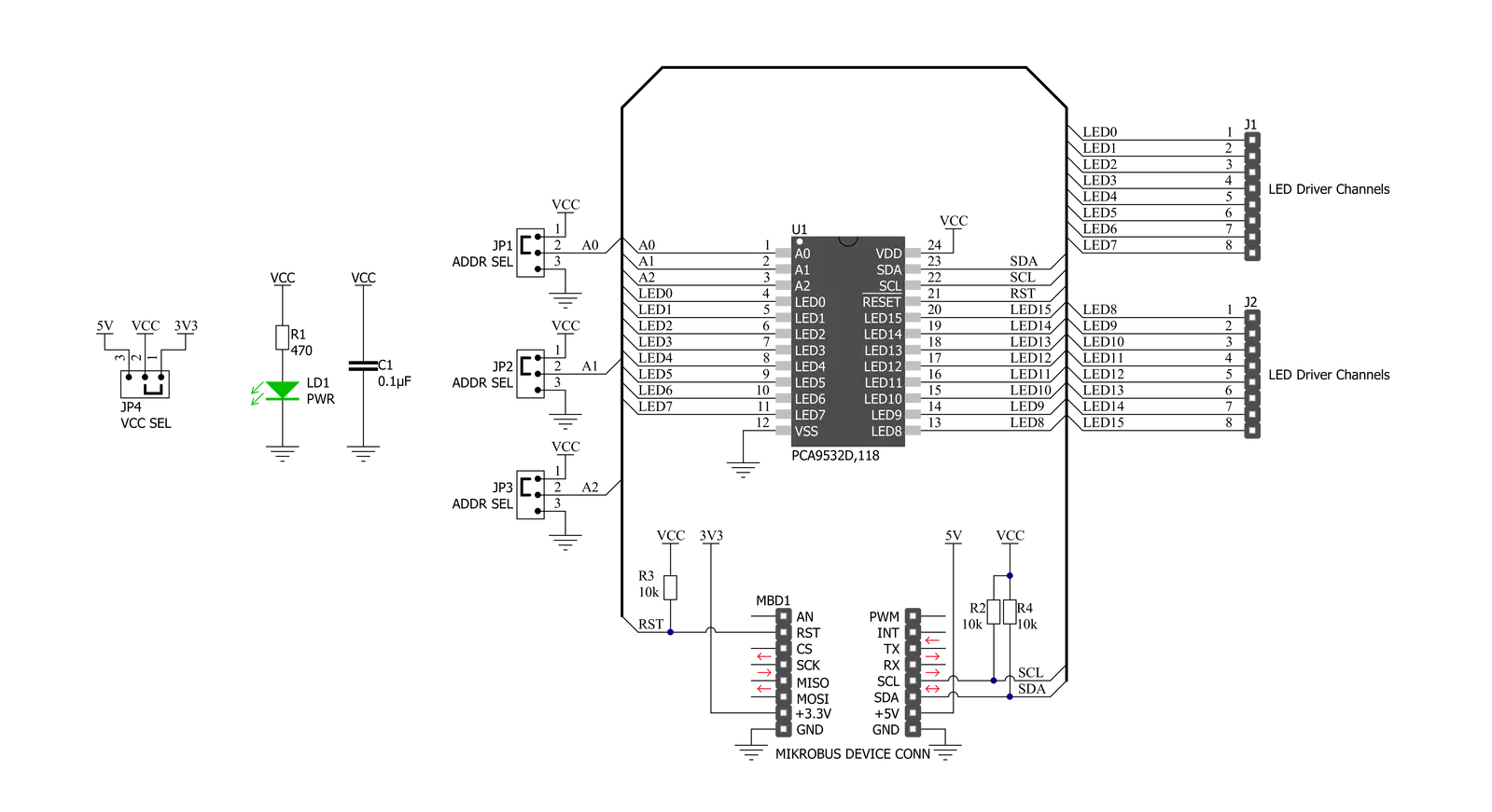
LED Driver 12 Click is based on the PCA9532, a 16-bit I2C-configurable LED dimmer from NXP Semiconductors. The PCA9532 has two fully programmable PWM controllers that control up to 16 LED channels, switching each of the LEDs ON and OFF independently. Each LED output, 16 LED drivers presented on two 1x8 male headers, with a maximum output current of 25mA per channel, has a programmable period ranging from 0.6Hz to 152Hz and a programmable duty cycle from 0 to 100%, which means that the LEDs can be set to blink steadily and visibly, or dimmed. Any bits not used for controlling the LED channels can be used for general-purpose parallel Input/Output (GPIO)
expansion, providing a simple solution when additional I/O is needed for some power switches, sensors, push-buttons, alarm monitoring, fans, or other applications. LED Driver 12 Click communicates with MCU using the standard I2C 2-Wire interface that supports Standard-Mode (100 kHz) and Fast-Mode (400 kHz) operation. The PCA9532 has a 7-bit slave address with the first five MSBs fixed to 1100. The address pins A0, A1, and A2 are programmed by the user and determine the value of the last three LSBs of the slave address, which can be selected by onboard SMD jumpers labeled as ADDR SEL, allowing selection of the slave address LSBs. Alongside the internal
Power-On Reset (POR) function, this board also has an active-low reset signal routed on the RST pin of the mikroBUS™ socket used to recover from a bus-fault condition. When this signal is asserted low, the PCA9532 resets its registers alongside the I2C state machine and deselects all channels. This Click board™ can operate with either 3.3V or 5V logic voltage levels selected via the VCC SEL jumper. This way, both 3.3V and 5V capable MCUs can use the communication lines properly. Also, this Click board™ comes equipped with a library containing easy-to-use functions and an example code that can be used as a reference for further development.


Features overview
Development board
Clicker 2 for Kinetis is a compact starter development board that brings the flexibility of add-on Click boards™ to your favorite microcontroller, making it a perfect starter kit for implementing your ideas. It comes with an onboard 32-bit ARM Cortex-M4F microcontroller, the MK64FN1M0VDC12 from NXP Semiconductors, two mikroBUS™ sockets for Click board™ connectivity, a USB connector, LED indicators, buttons, a JTAG programmer connector, and two 26-pin headers for interfacing with external electronics. Its compact design with clear and easily recognizable silkscreen markings allows you to build gadgets with unique functionalities and
features quickly. Each part of the Clicker 2 for Kinetis development kit contains the components necessary for the most efficient operation of the same board. In addition to the possibility of choosing the Clicker 2 for Kinetis programming method, using a USB HID mikroBootloader or an external mikroProg connector for Kinetis programmer, the Clicker 2 board also includes a clean and regulated power supply module for the development kit. It provides two ways of board-powering; through the USB Micro-B cable, where onboard voltage regulators provide the appropriate voltage levels to each component on the board, or
using a Li-Polymer battery via an onboard battery connector. All communication methods that mikroBUS™ itself supports are on this board, including the well-established mikroBUS™ socket, reset button, and several user-configurable buttons and LED indicators. Clicker 2 for Kinetis is an integral part of the Mikroe ecosystem, allowing you to create a new application in minutes. Natively supported by Mikroe software tools, it covers many aspects of prototyping thanks to a considerable number of different Click boards™ (over a thousand boards), the number of which is growing every day.

Microcontroller Overview
MCU Card / MCU

Architecture
ARM Cortex-M4
MCU Memory (KB)
1024
Silicon Vendor
NXP
Pin count
121
RAM (Bytes)
262144
Used MCU Pins
mikroBUS™ mapper
Take a closer look
Click board™ Schematic
Step by step
Project assembly

Start by selecting your development board and Click board™. Begin with the Clicker 2 for Kinetis as your development board.


Software Support
Library Description
This library contains API for LED Driver 12 Click driver.
Key functions:
leddriver12_set_led_config- This function sets the specified LED configleddriver12_set_led_port_config- This function sets the specified LED port configleddriver12_set_blink_period_pwm_0- This function sets the blink period of PWM 0 function
Open Source
Code example
The complete application code and a ready-to-use project are available through the NECTO Studio Package Manager for direct installation in the NECTO Studio. The application code can also be found on the MIKROE GitHub account.
/*!
 * @file main.c
 * @brief LEDDriver12 Click example
 *
 * # Description
 * This example demonstrates the use of LED Driver 12 Click board.
 *
 * The demo application is composed of two sections :
 *
 * ## Application Init
 * Initializes the driver and performs the Click default configuration which turns OFF
 * the LEDs 0 to 7, configures LEDs 8 to 11 for PWM0, and LEDs 12 to 15 for PWM1 settings.
 * PWM0 is set at half duty cycle with a one-second blinking period, while PWM1 is configured
 * for a quarter of duty cycle with a half-second blinking period.
 *
 * ## Application Task
 * Toggles the LEDs 0-7 every 2 seconds and displays their state on the USB UART.
 *
 * @author Stefan Filipovic
 *
 */

#include "board.h"
#include "log.h"
#include "leddriver12.h"

static leddriver12_t leddriver12;
static log_t logger;

void application_init ( void )
{
    log_cfg_t log_cfg;  /**< Logger config object. */
    leddriver12_cfg_t leddriver12_cfg;  /**< Click config object. */

    /**
     * Logger initialization.
     * Default baud rate: 115200
     * Default log level: LOG_LEVEL_DEBUG
     * @note If USB_UART_RX and USB_UART_TX
     * are defined as HAL_PIN_NC, you will
     * need to define them manually for log to work.
     * See @b LOG_MAP_USB_UART macro definition for detailed explanation.
     */
    LOG_MAP_USB_UART( log_cfg );
    log_init( &logger, &log_cfg );
    log_info( &logger, " Application Init " );

    // Click initialization.
    leddriver12_cfg_setup( &leddriver12_cfg );
    LEDDRIVER12_MAP_MIKROBUS( leddriver12_cfg, MIKROBUS_1 );
    if ( I2C_MASTER_ERROR == leddriver12_init( &leddriver12, &leddriver12_cfg ) )
    {
        log_error( &logger, " Communication init." );
        for ( ; ; );
    }

    if ( LEDDRIVER12_ERROR == leddriver12_default_cfg ( &leddriver12 ) )
    {
        log_error( &logger, " Default configuration." );
        for ( ; ; );
    }

    log_info( &logger, " Application Task " );
}

void application_task ( void )
{
    leddriver12_set_led_port_config ( &leddriver12, LEDDRIVER12_LED0_TO_3, LEDDRIVER12_LED_ON );
    leddriver12_set_led_port_config ( &leddriver12, LEDDRIVER12_LED4_TO_7, LEDDRIVER12_LED_ON );
    log_printf ( &logger, " LEDs 0-7 turns ON \r\n" );
    Delay_ms ( 1000 );
    Delay_ms ( 1000 );
    leddriver12_set_led_port_config ( &leddriver12, LEDDRIVER12_LED0_TO_3, LEDDRIVER12_LED_OFF );
    leddriver12_set_led_port_config ( &leddriver12, LEDDRIVER12_LED4_TO_7, LEDDRIVER12_LED_OFF );
    log_printf ( &logger, " LEDs 0-7 turns OFF \r\n\n" );
    Delay_ms ( 1000 );
    Delay_ms ( 1000 );
}

int main ( void )
{
    /* Do not remove this line or clock might not be set correctly. */
    #ifdef PREINIT_SUPPORTED
    preinit();
    #endif

    application_init( );

    for ( ; ; )
    {
        application_task( );
    }

    return 0;
}

// ------------------------------------------------------------------------ END
Additional Support
Resources
Category:LED Drivers


