Achieve superior performance in every brushed application with TB67H400AFTG and MK64FN1M0VDC12
Unlock the motor's true capabilities

Published May 31, 2023
Click board™
DC MOTOR 7 Click
Dev. board
Clicker 2 for Kinetis
Compiler
NECTO Studio
MCU
MK64FN1M0VDC12
Seize the opportunity to optimize your motorized system. Employ an alternative mode of this solution to use H-Bridges in parallel, receiving twice as much power!
A
A
Hardware Overview
How does it work?
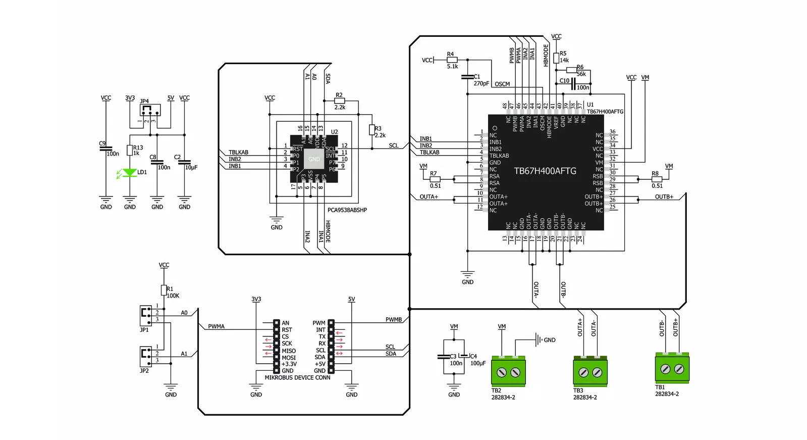
DC MOTOR 7 Click is based on the TB67H400AFTG, a PWM chopper-type brushed DC motor driver from Toshiba Semiconductor. This IC uses a proprietary BiCD manufacturing process, allowing this IC to be powered by a wide range of supply voltages, from 10V up to 47V. Due to the MOSFETs' very low ON resistance, the TB67H400AFTG can deliver up to 4A of current to the connected load. However, many external parameters affect both the maximum voltage and the current specifications, especially when the connected load is complex, such as the DC motor. This IC offers an alternative mode, where it can use its internal H-Bridges in parallel, offering twice as much power for a single motor. Before attempting to connect a single DC brushed motor, please refer to the datasheet of the TB67H400AFTG for precise connection instructions. DC MOTOR 7 click requires an external power supply for operation. The optimal voltage that should be used is 24V. Although the TB67H400AFTG driver has thermal and overcurrent protection, it is a temporary measure. A short-circuit at the output terminal may damage the Click board™. There are two output terminals used to connect DC motors and a power supply input terminal, where the external PSU can be connected, with respect to the polarity marked on the Click board™ itself (bottom side). Brushed DC motors are typically made with only two conductors to supply the motor with power, so even controlling the direction can be
challenging in some situations. Therefore, a specialized driver circuit is required. The TB67H400AFTG utilizes two sensing resistors (one for each channel) and an internally generated PWM signal to regulate the current through the motor. This results in better efficiency and less heat dissipation and provides control over the motor's torque, direction, and speed. Each motor is driven by the internal H-Bridge, which is controlled by the control logic section of the TB67H400AFTG IC. The motor control logic section regulates the current by opening and closing the specific MOSFETs of the H-Bridge, allowing the current through the coils to rise to a certain point (charging) to circulate between the coils and the driver until a specified point of time reached (slow decay), and then to return the remaining energy to the power supply (fast decay). The whole cycle is timed by pulses of the PWM signal derived from the internal oscillator. The TB67H400AFTG exposes six control pins to the microcontroller (MCU): PWMA, PWMB, INA1, INA2, INB1, and INB2. By changing the logic states on these pins, the MCU can control both connected motors independently. Besides a detailed explanation of the operating modes, the TB67H400AFTG datasheet also provides a truth table that explains the effects of logic states on these pins. Since the TB67H400AFTG IC has six different control pins, an additional port expander IC is required to access all these pins.
The PWMA and PWMB pins are routed to the mikroBUS™ RST and PWM pins, respectively, while the rest of the control pins (INA1, INA2, INB1, and INB2) are accessible via the PCA9538A, an 8-bit I2C port expander by NXP Semiconductors. In addition, the HBMODE pin used to select the single or dual operating mode (Large Mode or Small Mode) and the TBLKAB pin used to set the blanking interval are also available over the PCA9538A IC. Logic states on the PCA9538A pins can be easily set over the I2C interface, allowing to quickly change states on all the control pins of the TB67H400AFTG IC using a single command over the I2C interface. Please note that the state of the HBMODE pin should not be altered once the Click board™ is powered up and initialized. The slave I2C address of the PCA9538A can be changed. Two LSB of the I2C address can be set to 0 or 1 by switching SMD jumpers on the Click board™. This allows four different 7-bit I2C addresses to be selected from 0x70 to 0x73. This Click board™ can operate with either 3.3V or 5V logic voltage levels selected via the SMD jumper. This way, both 3.3V and 5V capable MCUs can use the communication lines properly. However, the Click board™ comes equipped with a library containing easy-to-use functions and an example code that can be used, as a reference, for further development.

Features overview
Development board
Clicker 2 for Kinetis is a compact starter development board that brings the flexibility of add-on Click boards™ to your favorite microcontroller, making it a perfect starter kit for implementing your ideas. It comes with an onboard 32-bit ARM Cortex-M4F microcontroller, the MK64FN1M0VDC12 from NXP Semiconductors, two mikroBUS™ sockets for Click board™ connectivity, a USB connector, LED indicators, buttons, a JTAG programmer connector, and two 26-pin headers for interfacing with external electronics. Its compact design with clear and easily recognizable silkscreen markings allows you to build gadgets with unique functionalities and
features quickly. Each part of the Clicker 2 for Kinetis development kit contains the components necessary for the most efficient operation of the same board. In addition to the possibility of choosing the Clicker 2 for Kinetis programming method, using a USB HID mikroBootloader or an external mikroProg connector for Kinetis programmer, the Clicker 2 board also includes a clean and regulated power supply module for the development kit. It provides two ways of board-powering; through the USB Micro-B cable, where onboard voltage regulators provide the appropriate voltage levels to each component on the board, or
using a Li-Polymer battery via an onboard battery connector. All communication methods that mikroBUS™ itself supports are on this board, including the well-established mikroBUS™ socket, reset button, and several user-configurable buttons and LED indicators. Clicker 2 for Kinetis is an integral part of the Mikroe ecosystem, allowing you to create a new application in minutes. Natively supported by Mikroe software tools, it covers many aspects of prototyping thanks to a considerable number of different Click boards™ (over a thousand boards), the number of which is growing every day.

Microcontroller Overview
MCU Card / MCU

Architecture
ARM Cortex-M4
MCU Memory (KB)
1024
Silicon Vendor
NXP
Pin count
121
RAM (Bytes)
262144
You complete me!
Accessories
DC Gear Motor - 430RPM (3-6V) represents an all-in-one combination of a motor and gearbox, where the addition of gear leads to a reduction of motor speed while increasing the torque output. This gear motor has a spur gearbox, making it a highly reliable solution for applications with lower torque and speed requirements. The most critical parameters for gear motors are speed, torque, and efficiency, which are, in this case, 520RPM with no load and 430RPM at maximum efficiency, alongside a current of 60mA and a torque of 50g.cm. Rated for a 3-6V operational voltage range and clockwise/counterclockwise rotation direction, this motor represents an excellent solution for many functions initially performed by brushed DC motors in robotics, medical equipment, electric door locks, and much more.

Used MCU Pins
mikroBUS™ mapper
Take a closer look
Click board™ Schematic
Step by step
Project assembly

Start by selecting your development board and Click board™. Begin with the Clicker 2 for Kinetis as your development board.


Track your results in real time
Application Output
1. Application Output - In Debug mode, the 'Application Output' window enables real-time data monitoring, offering direct insight into execution results. Ensure proper data display by configuring the environment correctly using the provided tutorial.

2. UART Terminal - Use the UART Terminal to monitor data transmission via a USB to UART converter, allowing direct communication between the Click board™ and your development system. Configure the baud rate and other serial settings according to your project's requirements to ensure proper functionality. For step-by-step setup instructions, refer to the provided tutorial.

3. Plot Output - The Plot feature offers a powerful way to visualize real-time sensor data, enabling trend analysis, debugging, and comparison of multiple data points. To set it up correctly, follow the provided tutorial, which includes a step-by-step example of using the Plot feature to display Click board™ readings. To use the Plot feature in your code, use the function: plot(*insert_graph_name*, variable_name);. This is a general format, and it is up to the user to replace 'insert_graph_name' with the actual graph name and 'variable_name' with the parameter to be displayed.

Software Support
Library Description
This library contains API for DC MOTOR 7 Click driver.
Key functions:
dcmotor7_set_port- Functions for set portdcmotor7_go_to_stand_by_mode- Function for setting the motor in stand modedcmotor7_set_pwm_motor_b- Function for set PWM value for motor B
Open Source
Code example
The complete application code and a ready-to-use project are available through the NECTO Studio Package Manager for direct installation in the NECTO Studio. The application code can also be found on the MIKROE GitHub account.
/*!
 * \file
 * \brief DcMotor7 Click example
 *
 * # Description
 * This application is a dual brushed DC motor driving.
 *
 * The demo application is composed of two sections :
 *
 * ## Application Init
 * Initialization driver init, enabled all output port, sets H-Bridge operation mode and Motor Digital tblk
 *
 * ## Application Task
 * Set the motor A and the motor B to rotate clockwise and in the Counte clockwise direction,
 * and between the change of direction, the motor stops the motor.
 *
 * *note:*
 * VM input - 10 V (min) to 47 V (max)
 *
 * \author MikroE Team
 *
 */
// ------------------------------------------------------------------- INCLUDES

#include "board.h"
#include "dcmotor7.h"

// ------------------------------------------------------------------ VARIABLES

static dcmotor7_t dcmotor7;

// ------------------------------------------------------ APPLICATION FUNCTIONS

void application_init ( void )
{
    dcmotor7_cfg_t cfg;

    //  Click initialization.

    dcmotor7_cfg_setup( &cfg );
    DCMOTOR7_MAP_MIKROBUS( cfg, MIKROBUS_1 );
    dcmotor7_init( &dcmotor7, &cfg );

    dcmotor7_default_cfg( &dcmotor7 );
}

void application_task ( void )
{
    dcmotor7_set_motor( &dcmotor7, DCMOTOR7_MOTOR_A, 0, 1 );
    dcmotor7_set_motor( &dcmotor7, DCMOTOR7_MOTOR_B, 0, 1 );
    Delay_ms ( 500 );

    dcmotor7_motor_stop( &dcmotor7, DCMOTOR7_MOTOR_A );
    dcmotor7_motor_stop( &dcmotor7, DCMOTOR7_MOTOR_B );
    Delay_ms ( 1000 );
    Delay_ms ( 1000 );

    dcmotor7_set_motor( &dcmotor7, DCMOTOR7_MOTOR_A, 1, 0 );
    dcmotor7_set_motor( &dcmotor7, DCMOTOR7_MOTOR_B, 1, 0 );
    Delay_ms ( 500 );

    dcmotor7_motor_stop( &dcmotor7, DCMOTOR7_MOTOR_A );
    dcmotor7_motor_stop( &dcmotor7, DCMOTOR7_MOTOR_B );
    Delay_ms ( 1000 );
    Delay_ms ( 1000 );
}

int main ( void )
{
    /* Do not remove this line or clock might not be set correctly. */
    #ifdef PREINIT_SUPPORTED
    preinit();
    #endif

    application_init( );

    for ( ; ; )
    {
        application_task( );
    }

    return 0;
}

// ------------------------------------------------------------------------ END


