Enjoy peace of mind with temperature data in reserve thanks to CAT34TS02 and MSP432P401R
Measure, store, and innovate

Published Nov 08, 2023
Click board™
Temp-Log 5 Click
Dev. board
UNI Clicker
Compiler
NECTO Studio
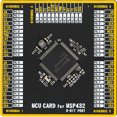
MCU
MSP432P401R
We ensure your temperature insights are preserved for the long run with our extended EEPROM memory.
A
A
Hardware Overview
How does it work?
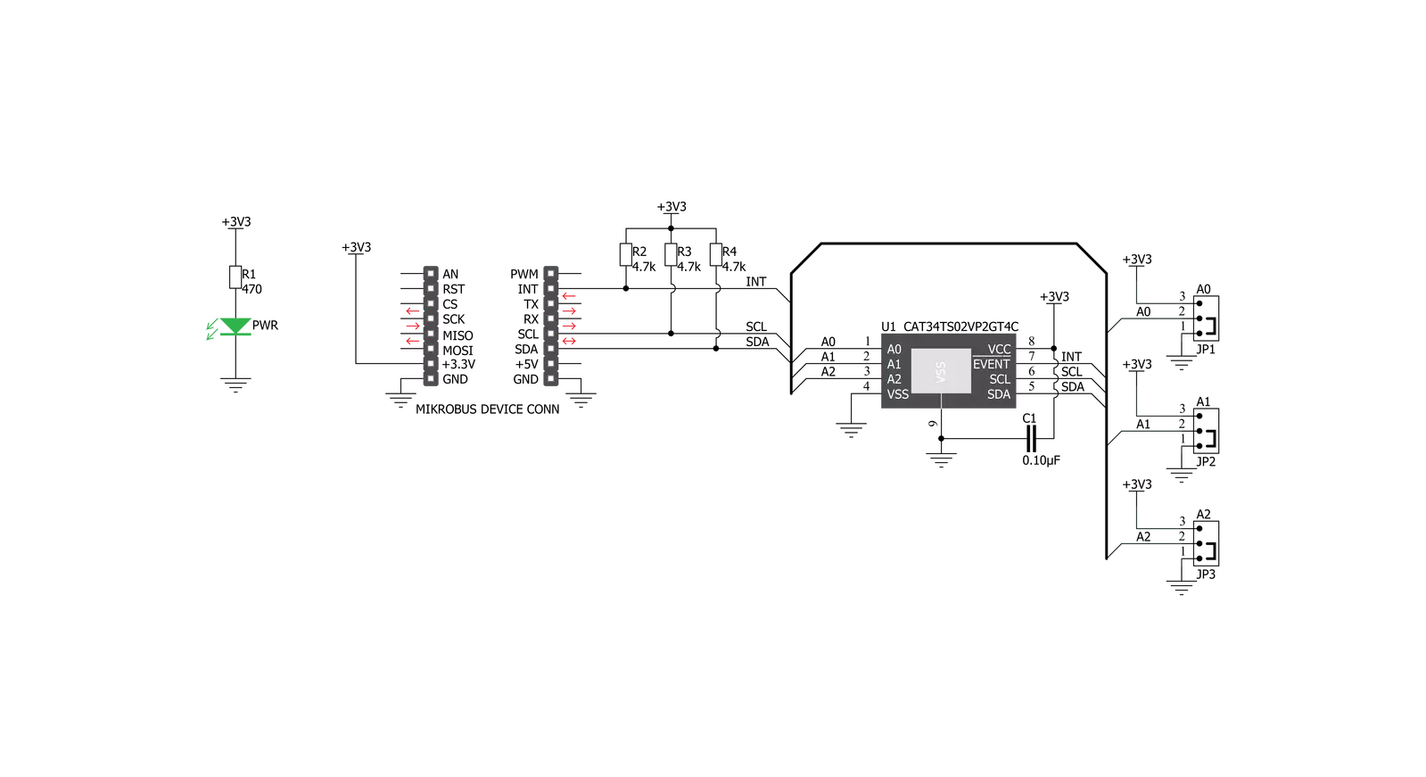
Temp-Log 5 Click is based on the CAT34TS02, an accurate temperature sensor IC with integrated serial presence detect EEPROM from ON semiconductor that combines a JC42.4 compliant Temperature Sensor (TS) with 2 Kb of Serial Presence Detect (SPD) EEPROM. Temperature sensor measures and stores temperatures at least 10 times in second, allowing it to be retrieved by the host MCU via the I2C interface. The result can be compared to critical limits, stored into internal registers. This allows the sensor to reduce the processing workload of the host MCU by employing the trigger limits mechanism: by asserting the EVENT line to a LOW logic level, the CAT34TS02 is able to wake up the host MCU, reducing the power consumption. The EVENT pin is routed to the INT pin of the mikroBUS™. The CAT34TS02 IC can be configured to trigger an EVENT in three different modes: Interrupt mode, Comparator mode,
and Critical Temperature mode. When set in the Interrupt Mode, the EVENT output will be asserted every time the temperature crosses one of the alarm limits. Once the temperature exceeds the critical limit, the EVENT remains asserted as long as the temperature stays above the critical limit. The EVENT can be cleared by setting a bit in a corresponding register (must be cleared by the software). However the pin will remain asserted as long as the temperature exceeds the critical limits. In the Comparator mode, the EVENT pin is asserted whenever the temperature is outside the predefined limit values, and deasserted as soon as the temperature drops under the limit (no need to clear the bit by the software). If set in the Critical Temperature Mode, the EVENT pin will be asserted only if the temperature exceeds a critical threshold limit. The limit values can be programmed via the corresponding registers. CAT34TS02 IC uses the
I2C/SMBus protocols to communicate with the host MCU. Its I2C bus pins are routed to the mikroBUS™ I2C pins and are pulled to a HIGH logic level by the onboard resistors. The I2C slave address of the CAT34TS02 IC can be selected by ADDR pins A0, A1 and A2: LOW logic level clears the corresponding address bit (GND), while HIGH logic level sets the bit (VCC). This can be done using a group of onboard jumpers, positioned under the label ADDR SEL. This Click board™ can be operated only with a 3.3V logic voltage level. The board must perform appropriate logic voltage level conversion before using MCUs with different logic levels. Also, it comes equipped with a library containing functions and an example code that can be used as a reference for further development.

Features overview
Development board
UNI Clicker is a compact development board designed as a complete solution that brings the flexibility of add-on Click boards™ to your favorite microcontroller, making it a perfect starter kit for implementing your ideas. It supports a wide range of microcontrollers, such as different ARM, PIC32, dsPIC, PIC, and AVR from various vendors like Microchip, ST, NXP, and TI (regardless of their number of pins), four mikroBUS™ sockets for Click board™ connectivity, a USB connector, LED indicators, buttons, a debugger/programmer connector, and two 26-pin headers for interfacing with external electronics. Thanks to innovative manufacturing technology, it allows you to build
gadgets with unique functionalities and features quickly. Each part of the UNI Clicker development kit contains the components necessary for the most efficient operation of the same board. In addition to the possibility of choosing the UNI Clicker programming method, using a third-party programmer or CODEGRIP/mikroProg connected to onboard JTAG/SWD header, the UNI Clicker board also includes a clean and regulated power supply module for the development kit. It provides two ways of board-powering; through the USB Type-C (USB-C) connector, where onboard voltage regulators provide the appropriate voltage levels to each component on the board, or using a Li-Po/Li
Ion battery via an onboard battery connector. All communication methods that mikroBUS™ itself supports are on this board (plus USB HOST/DEVICE), including the well-established mikroBUS™ socket, a standardized socket for the MCU card (SiBRAIN standard), and several user-configurable buttons and LED indicators. UNI Clicker is an integral part of the Mikroe ecosystem, allowing you to create a new application in minutes. Natively supported by Mikroe software tools, it covers many aspects of prototyping thanks to a considerable number of different Click boards™ (over a thousand boards), the number of which is growing every day.

Microcontroller Overview
MCU Card / MCU
Type
8th Generation
Architecture
ARM Cortex-M4
MCU Memory (KB)
256
Silicon Vendor
Texas Instruments
Pin count
100
RAM (Bytes)
65536
Used MCU Pins
mikroBUS™ mapper
Take a closer look
Click board™ Schematic
Step by step
Project assembly

Start by selecting your development board and Click board™. Begin with the UNI Clicker as your development board.


Software Support
Library Description
This library contains API for Temp-Log 5 Click driver.
Key functions:
templog5_write_eeprom- This function write data to the EEPROM address.templog5_read_eeprom- This function read data to the EEPROM address.templog5_read_data- This function read from the TS register.
Open Source
Code example
The complete application code and a ready-to-use project are available through the NECTO Studio Package Manager for direct installation in the NECTO Studio. The application code can also be found on the MIKROE GitHub account.
/*!
 * \file
 * \brief TempLog5 Click example
 *
 * # Description
 * This Click measures and stores temperatures at least 10 times in second,
 * allowing it to be retrieved by the host MCU via the I2C interface.
 * The result can be compared to critical limits, stored into internal registers.
 *
 * The demo application is composed of two sections :
 *
 * ## Application Init
 * Initializes driver init, Test comunication, EEPROM write/read test and
 * configuration device for measurement.
 *
 * ## Application Task
 * Reads Temperature data and logs data to the USBUART every 1 sec.
 *
 *
 * \author MikroE Team
 *
 */
// ------------------------------------------------------------------- INCLUDES

#include "board.h"
#include "log.h"
#include "templog5.h"

// ------------------------------------------------------------------ VARIABLES

static templog5_t templog5;
static log_t logger;

// ------------------------------------------------------ APPLICATION FUNCTIONS

void application_init ( void )
{
    log_cfg_t log_cfg;
    templog5_cfg_t cfg;
    uint16_t tmp;
    uint8_t ee_test_write[1];
    uint8_t ee_test_read[1];

    /**
     * Logger initialization.
     * Default baud rate: 115200
     * Default log level: LOG_LEVEL_DEBUG
     * @note If USB_UART_RX and USB_UART_TX
     * are defined as HAL_PIN_NC, you will
     * need to define them manually for log to work.
     * See @b LOG_MAP_USB_UART macro definition for detailed explanation.
     */
    LOG_MAP_USB_UART( log_cfg );
    log_init( &logger, &log_cfg );
    log_info( &logger, "---- Application Init ----" );

    //  Click initialization.

    templog5_cfg_setup( &cfg );
    TEMPLOG5_MAP_MIKROBUS( cfg, MIKROBUS_1 );
    templog5_init( &templog5, &cfg );

    tmp = templog5_read_data( &templog5, TEMPLOG5_REG_MANUFACTURER_ID );

    if ( tmp == TEMPLOG5_MANUFACTURER_ID )
    {
        log_info( &logger, "Comunication OK!!!" );
    }
    else
    {
        log_info( &logger, "Comunication ERROR!!!" );
        while( 1 );
    }

    ee_test_write[ 0 ] = 0xAA;
    templog5_write_eeprom( &templog5, 0x10, &ee_test_write[ 0 ], 1 );
    Delay_ms ( 200 );

    templog5_read_eeprom( &templog5, 0x10, &ee_test_read[ 0 ], 1 );

    log_info( &logger," EEPROM TEST READ:  %u\r\n", ee_test_read[ 0 ] );

    templog5_default_cfg ( &templog5 );
}

void application_task ( void )
{
    float temperature;

    temperature = templog5_get_temperature( &templog5 );
    log_info( &logger,"Temperature:  %.2f\r\n", temperature );
    Delay_ms ( 1000 );
}

int main ( void )
{
    /* Do not remove this line or clock might not be set correctly. */
    #ifdef PREINIT_SUPPORTED
    preinit();
    #endif

    application_init( );

    for ( ; ; )
    {
        application_task( );
    }

    return 0;
}


// ------------------------------------------------------------------------ END
Additional Support
Resources
Category:Temperature & humidity


