Explore how GP2Y0A60SZ0F and STM32F071VB takes distance measurement to a new heights
Seeing with infrared eyes

Published Sep 19, 2023
Click board™
IR Distance Click
Dev. board
UNI Clicker
Compiler
NECTO Studio
MCU
STM32F071VB
Simplify distance measurement challenges with infrared sensors, paving the way for smarter, more efficient systems across industries
A
A
Hardware Overview
How does it work?
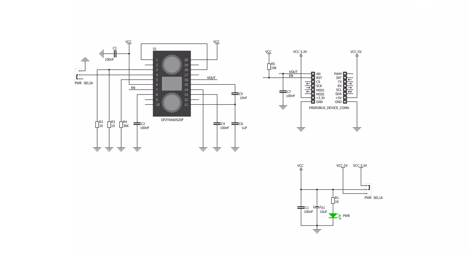
IR Distance Click is based on the GP2Y0A60SZ0F, a distance-measuring sensor unit from Sharp. The sensor provides a voltage corresponding to the detection distance, which is why it can also be used as a proximity sensor. The triangulation method of measuring the distance means the determination of the location of an object by forming triangles to the point of known points. In the case of the GP2Y0A60SZ0F, the IR LED emits a narrow light beam and, after reflecting from an object, is directed to the sensor lens of the PSD. Depending on the object, the angle of the reflected light will be different. The conductivity
of the PSD depends on the position where the reflected beam falls and is afterward converted to voltage, where the distance can be calculated using an analog-digital converter. The IR Distance Click communicates with the host MCU by sending analog values over the OUT pin of the mikroBUS™ socket. The OUT pin provides information to the MCU about the presence of an object and its distance, where the output of the distance sensor is inversely proportional, meaning that when the distance grows, the output decreases. The main control pin of the sensor can be accessed over the EN pin of the mikroBUS™
socket, thus enabling the sensor to work. This Click board™ can operate with either 3.3V or 5V logic voltage levels selected via the PWR SEL jumpers. This way, both 3.3V and 5V capable MCUs can use the communication lines properly. Note that all the jumpers' positions must be on the same side, or the Click board™ may become unresponsive. Also, this Click board™ comes equipped with a library containing easy-to-use functions and an example code that can be used as a reference for further development.

Features overview
Development board
UNI Clicker is a compact development board designed as a complete solution that brings the flexibility of add-on Click boards™ to your favorite microcontroller, making it a perfect starter kit for implementing your ideas. It supports a wide range of microcontrollers, such as different ARM, PIC32, dsPIC, PIC, and AVR from various vendors like Microchip, ST, NXP, and TI (regardless of their number of pins), four mikroBUS™ sockets for Click board™ connectivity, a USB connector, LED indicators, buttons, a debugger/programmer connector, and two 26-pin headers for interfacing with external electronics. Thanks to innovative manufacturing technology, it allows you to build
gadgets with unique functionalities and features quickly. Each part of the UNI Clicker development kit contains the components necessary for the most efficient operation of the same board. In addition to the possibility of choosing the UNI Clicker programming method, using a third-party programmer or CODEGRIP/mikroProg connected to onboard JTAG/SWD header, the UNI Clicker board also includes a clean and regulated power supply module for the development kit. It provides two ways of board-powering; through the USB Type-C (USB-C) connector, where onboard voltage regulators provide the appropriate voltage levels to each component on the board, or using a Li-Po/Li
Ion battery via an onboard battery connector. All communication methods that mikroBUS™ itself supports are on this board (plus USB HOST/DEVICE), including the well-established mikroBUS™ socket, a standardized socket for the MCU card (SiBRAIN standard), and several user-configurable buttons and LED indicators. UNI Clicker is an integral part of the Mikroe ecosystem, allowing you to create a new application in minutes. Natively supported by Mikroe software tools, it covers many aspects of prototyping thanks to a considerable number of different Click boards™ (over a thousand boards), the number of which is growing every day.

Microcontroller Overview
MCU Card / MCU
Type
8th Generation
Architecture
ARM Cortex-M0
MCU Memory (KB)
128
Silicon Vendor
STMicroelectronics
Pin count
100
RAM (Bytes)
16384
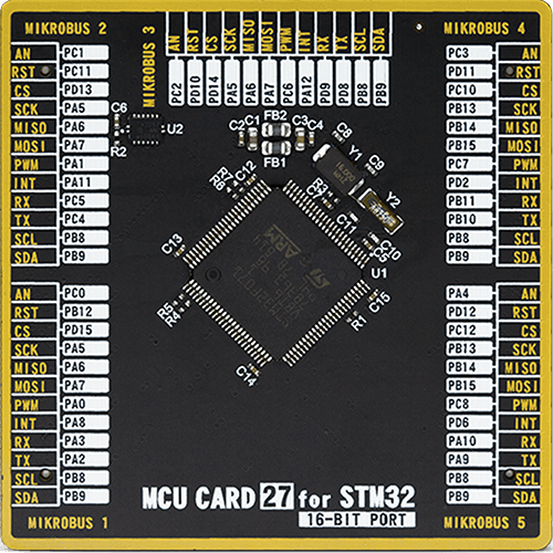
Used MCU Pins
mikroBUS™ mapper
Take a closer look
Click board™ Schematic
Step by step
Project assembly

Start by selecting your development board and Click board™. Begin with the UNI Clicker as your development board.


Track your results in real time
Application Output
1. Application Output - In Debug mode, the 'Application Output' window enables real-time data monitoring, offering direct insight into execution results. Ensure proper data display by configuring the environment correctly using the provided tutorial.

2. UART Terminal - Use the UART Terminal to monitor data transmission via a USB to UART converter, allowing direct communication between the Click board™ and your development system. Configure the baud rate and other serial settings according to your project's requirements to ensure proper functionality. For step-by-step setup instructions, refer to the provided tutorial.

3. Plot Output - The Plot feature offers a powerful way to visualize real-time sensor data, enabling trend analysis, debugging, and comparison of multiple data points. To set it up correctly, follow the provided tutorial, which includes a step-by-step example of using the Plot feature to display Click board™ readings. To use the Plot feature in your code, use the function: plot(*insert_graph_name*, variable_name);. This is a general format, and it is up to the user to replace 'insert_graph_name' with the actual graph name and 'variable_name' with the parameter to be displayed.

Software Support
Library Description
This library contains API for IR Distance Click driver.
Key functions:
irdistance_enable- This function enable distance measuring sensorirdistance_read_adc- This function reads ADC data using analog_in_read functionirdistance_get_voltage_out- This function calculate the voltage output of distance measuring sensor
Open Source
Code example
The complete application code and a ready-to-use project are available through the NECTO Studio Package Manager for direct installation in the NECTO Studio. The application code can also be found on the MIKROE GitHub account.
/*!
 * \file
 * \brief IR distance Click example
 *
 * # Description
 * The Click board outputs an analog voltage corresponding to the distance of the object
 * (through the mikroBUS AN pin). An Enable (EN) pin is also utilized.
 *
 * The demo application is composed of two sections :
 *
 * ## Application Init
 * Initialization driver enables GPIO, enable IR sensor, initialization ADC, also write log.
 *
 * ## Application Task
 * This is an example which demonstrates the use of IR Distance Click board.
 * IR Distance Click reads and displays ADC value.
 * Results are being sent to the Usart Terminal where you can track their changes.
 * All data logs on USB uart change for every 1 sec.
 *
 *
 * \author MikroE Team
 *
 */
// ------------------------------------------------------------------- INCLUDES

#include "board.h"
#include "log.h"
#include "irdistance.h"

// ------------------------------------------------------------------ VARIABLES

static irdistance_t irdistance;
static log_t logger;

static uint16_t adc_val;
static float voltage_val;

// ------------------------------------------------------ APPLICATION FUNCTIONS

void application_init ( void )
{
    log_cfg_t log_cfg;
    irdistance_cfg_t cfg;

    /**
     * Logger initialization.
     * Default baud rate: 115200
     * Default log level: LOG_LEVEL_DEBUG
     * @note If USB_UART_RX and USB_UART_TX
     * are defined as HAL_PIN_NC, you will
     * need to define them manually for log to work.
     * See @b LOG_MAP_USB_UART macro definition for detailed explanation.
     */
    LOG_MAP_USB_UART( log_cfg );
    log_init( &logger, &log_cfg );
    log_info( &logger, "---- Application Init ----" );

    //  Click initialization.

    irdistance_cfg_setup( &cfg );
    IRDISTANCE_MAP_MIKROBUS( cfg, MIKROBUS_1 );
    if ( irdistance_init( &irdistance, &cfg ) == ADC_ERROR )
    {
        log_info( &logger, "---- Application Init Error ----" );
        log_info( &logger, "---- Please, run program again ----" );

        for ( ; ; );
    }
    irdistance_enable_device( &irdistance );
    log_info( &logger, "---- Application Init Done ----\r\n" );

    voltage_val = 0;
    adc_val = 0;
}

void application_task ( void )
{
    if ( irdistance_read_adc( &irdistance, &adc_val ) != ADC_ERROR )
    {
        log_printf( &logger, " ADC value on the pin : %u\r\n", adc_val );
    }

    if ( irdistance_get_pin_voltage( &irdistance, &voltage_val ) != ADC_ERROR )
    {
        log_printf( &logger, " Voltage value on the pin : %.2f\r\n", voltage_val );
    }

    log_printf( &logger, "------------------------------\r\n" );
    Delay_ms ( 1000 );
}

int main ( void )
{
    /* Do not remove this line or clock might not be set correctly. */
    #ifdef PREINIT_SUPPORTED
    preinit();
    #endif

    application_init( );

    for ( ; ; )
    {
        application_task( );
    }

    return 0;
}


// ------------------------------------------------------------------------ END


