Create the ideal environment for a healthier, happier life with HDC2080 and PIC18F87J10
Your climate, your control, our expertise

Published Nov 29, 2024
Click board™
Temp&Hum 12 Click
Dev. board
UNI Clicker
Compiler
NECTO Studio
MCU
PIC18F87J10
Our technology and your comfort are perfectly aligned, bringing you the best in climate control solutions.
A
A
Hardware Overview
How does it work?
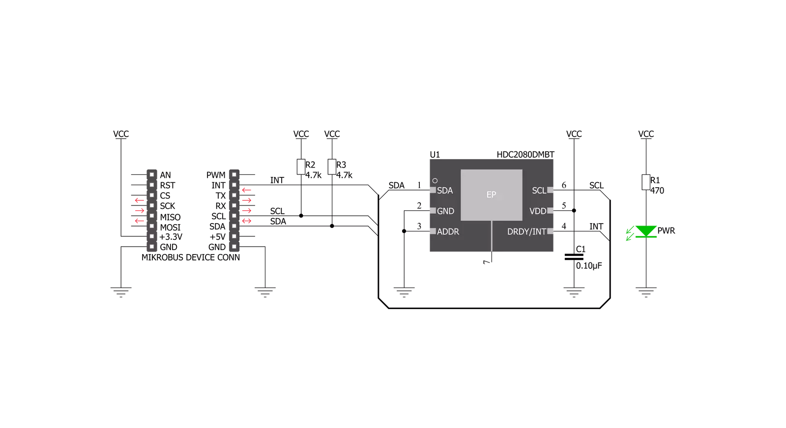
Temp&Hum 12 Click is based on the HDC2080, a Low Power Humidity and Temperature Digital Sensor from Texas Instruments. This sensor is factory calibrated to 2% relative humidity and 0.2°C temperature accuracy. It has an integrated heating element that is used to evaporate condensation, protecting the sensor that way. This heating element can be simply activated by setting a bit in the appropriate register. In the case when the heater is powered on, the typical current consumption is about 90mA. Internally, two sensors are connected to the two separated ADC sections, which can be set to sample measurements with the resolution of 9, 11 or 14 bits, based on the measurement time. The OTP memory holds the calibration coefficients that are applied to the measured value and the results are stored on the output registers, in the MSB/LSB format. These values are
then used in formulas found in the HDC2080 datasheet so that the final temperature or relative humidity data can be calculated. It is also possible to correct the offsets with custom values. HDC2080 IC uses the I2C protocol to communicate with the host MCU. Its I2C bus pins are routed to the mikroBUS™ I2C pins and are pulled to a HIGH logic level by the onboard resistors. The final I2C address of this IC is already determined by setting ADDR pin to GND (LOW logic level for 0). Temp&Hum 12 click supports programable temperature and humidity thresholds in the HDC2080 allow the device to send a hardware interrupt to wake up the microcontroller when necessary. In addition, the power consumption of the HDC2080 is significantly reduced, which helps to minimize self-heating and improve measurement accuracy. More information about these registers can be
found in the HDC2080 datasheet. HDC2080 IC itself is a very low power consumption device and it can work in two modes: sleep and active (measurement) mode. The device enters the sleep the mode as soon as possible, to save power. This makes the HDC2080 suitable to be used in battery-powered applications. In these applications, the HDC2080 spends most of the time in sleep mode, with the typical current consumption of 50 nA. While in the active mode, measurement can be configured either to automatic (with the predefined output data rate) or on-demand. In the automatic mode, the measurement is triggered in predefined time intervals, while on-demand measurement happens whenever the I2C command is sent. As soon as the single measurement is finished, the device falls back to the sleep mode.

Features overview
Development board
UNI Clicker is a compact development board designed as a complete solution that brings the flexibility of add-on Click boards™ to your favorite microcontroller, making it a perfect starter kit for implementing your ideas. It supports a wide range of microcontrollers, such as different ARM, PIC32, dsPIC, PIC, and AVR from various vendors like Microchip, ST, NXP, and TI (regardless of their number of pins), four mikroBUS™ sockets for Click board™ connectivity, a USB connector, LED indicators, buttons, a debugger/programmer connector, and two 26-pin headers for interfacing with external electronics. Thanks to innovative manufacturing technology, it allows you to build
gadgets with unique functionalities and features quickly. Each part of the UNI Clicker development kit contains the components necessary for the most efficient operation of the same board. In addition to the possibility of choosing the UNI Clicker programming method, using a third-party programmer or CODEGRIP/mikroProg connected to onboard JTAG/SWD header, the UNI Clicker board also includes a clean and regulated power supply module for the development kit. It provides two ways of board-powering; through the USB Type-C (USB-C) connector, where onboard voltage regulators provide the appropriate voltage levels to each component on the board, or using a Li-Po/Li
Ion battery via an onboard battery connector. All communication methods that mikroBUS™ itself supports are on this board (plus USB HOST/DEVICE), including the well-established mikroBUS™ socket, a standardized socket for the MCU card (SiBRAIN standard), and several user-configurable buttons and LED indicators. UNI Clicker is an integral part of the Mikroe ecosystem, allowing you to create a new application in minutes. Natively supported by Mikroe software tools, it covers many aspects of prototyping thanks to a considerable number of different Click boards™ (over a thousand boards), the number of which is growing every day.

Microcontroller Overview
MCU Card / MCU

Type
8th Generation
Architecture
PIC (8-bit)
MCU Memory (KB)
128
Silicon Vendor
Microchip
Pin count
80
RAM (Bytes)
3936
Used MCU Pins
mikroBUS™ mapper
Take a closer look
Click board™ Schematic
Step by step
Project assembly

Start by selecting your development board and Click board™. Begin with the UNI Clicker as your development board.


Track your results in real time
Application Output
1. Application Output - In Debug mode, the 'Application Output' window enables real-time data monitoring, offering direct insight into execution results. Ensure proper data display by configuring the environment correctly using the provided tutorial.

2. UART Terminal - Use the UART Terminal to monitor data transmission via a USB to UART converter, allowing direct communication between the Click board™ and your development system. Configure the baud rate and other serial settings according to your project's requirements to ensure proper functionality. For step-by-step setup instructions, refer to the provided tutorial.

3. Plot Output - The Plot feature offers a powerful way to visualize real-time sensor data, enabling trend analysis, debugging, and comparison of multiple data points. To set it up correctly, follow the provided tutorial, which includes a step-by-step example of using the Plot feature to display Click board™ readings. To use the Plot feature in your code, use the function: plot(*insert_graph_name*, variable_name);. This is a general format, and it is up to the user to replace 'insert_graph_name' with the actual graph name and 'variable_name' with the parameter to be displayed.

Software Support
Library Description
This library contains API for Temp&Hum 12 Click driver.
Key functions:
temphum12_get_temperature- Temperature datatemphum12_get_humidity- Relative Huminidy datatemphum12_get_intrrupt_state- Interrupt state
Open Source
Code example
The complete application code and a ready-to-use project are available through the NECTO Studio Package Manager for direct installation in the NECTO Studio. The application code can also be found on the MIKROE GitHub account.
/*!
 * \file
 * \brief TempHum12 Click example
 *
 * # Description
 * This application measures temperature and humidity.
 *
 * The demo application is composed of two sections :
 *
 * ## Application Init
 * Initializes driver init and configuration device for measurement.
 *
 * ## Application Task
 * Reads Temperature and Humidity data and this data logs to the USBUART every 1 sec.
 *
 * \author MikroE Team
 *
 */
// ------------------------------------------------------------------- INCLUDES

#include "board.h"
#include "log.h"
#include "temphum12.h"

// ------------------------------------------------------------------ VARIABLES

static temphum12_t temphum12;
static log_t logger;

// ------------------------------------------------------ APPLICATION FUNCTIONS

void application_init ( void )
{
    log_cfg_t log_cfg;
    temphum12_cfg_t cfg;
    uint16_t tmp;
    uint8_t read_reg[ 2 ];

    /**
     * Logger initialization.
     * Default baud rate: 115200
     * Default log level: LOG_LEVEL_DEBUG
     * @note If USB_UART_RX and USB_UART_TX
     * are defined as HAL_PIN_NC, you will
     * need to define them manually for log to work.
     * See @b LOG_MAP_USB_UART macro definition for detailed explanation.
     */
    LOG_MAP_USB_UART( log_cfg );
    log_init( &logger, &log_cfg );
    log_info( &logger, "---- Application Init ----" );

    //  Click initialization.

    temphum12_cfg_setup( &cfg );
    TEMPHUM12_MAP_MIKROBUS( cfg, MIKROBUS_1 );
    temphum12_init( &temphum12, &cfg );

    temphum12_default_cfg( &temphum12 );

    Delay_ms ( 1000 );
    Delay_ms ( 500 );
    log_printf( &logger, "--- Start measurement ----\r\n" );
}

void application_task ( void )
{
    float temperature;
    float humidity;

    temperature = temphum12_get_temperature( &temphum12,
                                             TEMPHUM12_TEMP_IN_CELSIUS );

    log_printf( &logger, "Temperature: %.2f \r\n", temperature );
    Delay_1sec( );

    humidity = temphum12_get_humidity( &temphum12 );

    log_printf( &logger, "Humidity: %.2f \r\n", humidity );

    log_printf( &logger, "-----------------------------\r\n" );
    Delay_1sec( );
}

int main ( void )
{
    /* Do not remove this line or clock might not be set correctly. */
    #ifdef PREINIT_SUPPORTED
    preinit();
    #endif

    application_init( );

    for ( ; ; )
    {
        application_task( );
    }

    return 0;
}

// ------------------------------------------------------------------------ END
Additional Support
Resources
Category:Temperature & humidity


