Unlock a new dimension in thermal perception with MLX90621 and ATmega2560
Seeing heat in a new light: Discover thermal infrared imaging!

Published Feb 12, 2024
Click board™
IR Grid Click
Dev. board
UNI Clicker
Compiler
NECTO Studio
MCU
ATmega2560
Experience a paradigm shift in temperature measurement and heat detection with our state-of-the-art thermal imaging technology, offering real-time, high-resolution insights for a multitude of applications
A
A
Hardware Overview
How does it work?
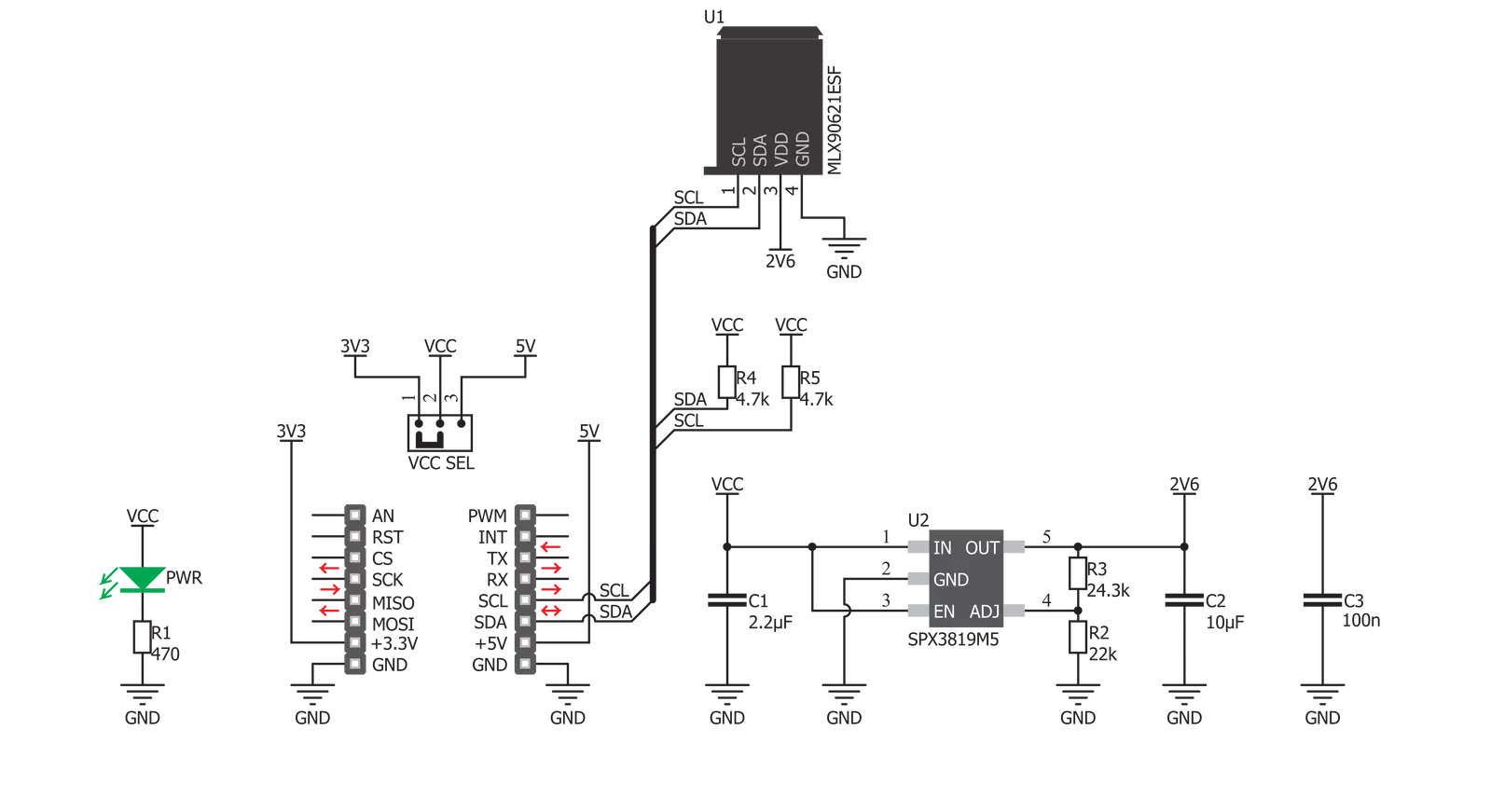
IR Grid Click is based on the MLX90621, a 16x4 IR array sensor from Melexis. This sensor consists of two separate ICs in TO39 package: one IC is the sensor itself, labeled as MLX90670, while the second IC is the 2Kbit EEPROM labeled as 24AA02, used to store all the compensation and calibration parameters. These sensors can measure temperature relative to the cold junction temperature, and for this reason, the MLX90621ESF IR sensor incorporates a PTAT (Proportional to Absolute Temperature) compensation sensor. The IR sensor array, as well as the PTAT sensor readings, are sampled by fast internal ADC and stored on the RAM, which can be accessed via the I2C. The resolution of the ADC can be programmed between 15bit and 18bit. The sensor IC supports the I2C FM+ mode with transfer rate up to 1000 kbps, while the EEPROM IC supports up to Fast Rate (400 kbps). The MLX90621ESF-BAD IR sensor used on this Click board™ offers 40˚ x 10˚ FOV, with the IR sensing elements arranged in a 4x16 grid. Each sensor measures the temperature in its individual FOV, allowing the host MCU to build a thermal image or calculate the temperature at each spot of the imaged scene. The measurement results are stored in the onboard RAM. 64 words, each 16 bits wide contains the result of the IR sensor measurements, and one word contains the PTAT measurement. The configuration register allows
configuring of the measurement parameters. This 16bit register contains bits that control the behavior of the sensor IC: the refresh rate, ADC resolution, measurement mode (continuous or step mode), sleep mode, I2C mode (FM or FM+), EEPROM disable/enable, etc. It also contains some flags, such as the POR/BOR (Power ON Reset/Brown Out Reset) indicator bit, and measurement in progress bit. For example, if the POR/BOR bit is set to 0, the initialization has to be repeated, as the calibration might not be valid any longer. The EEPROM IC contains all the necessary calibration parameters, as well as the content of the configuration register, that may be used between the POR cycles. The manufacturer advises storing of the EEPROM content in the RAM of the MCU before measurement, especially if faster refresh rates are used. A certain workflow has to be followed when operating this sensor. The workflow includes calculation of the compensation parameters that are stored in the EEPROM for each element. Those calculations include ambient temperature calculation, pixel offset calculation, pixel to pixel sensitivity difference compensation, object emissivity compensation, and object temperature calculation. The datasheet of the MLX90621ESF-BAD IR sensor contains these equations, which use the parameters stored in EEPROM. However, this Click board™ is supported by the library,
which contains functions that simplify working with this sensor. It should be noted that the sensor measures the IR emissivity of an object, so it is to expect that some materials cannot be accurately measured by this sensor due to their low emissivity, such as the aluminum. To better understand the emissivity property of the materials, a person wearing clothes, can be taken as an example: the measured temperature will reflect the clothes temperature, rather than the body temperature itself, which is known to be about 37 ˚C Care should be taken not to expose the Click board™ to a cold or hot air flow, as it will cause false readings of the real temperature. This sensor requires the temperature across the sensor package to be constant. The MLX90621ESF-BAD IR sensor uses 2.6V for optimal results. To provide 2.6V, this Click board™ is equipped with the SPX3819, a small low noise LDO, which converts either 3.3V or 5V from the mikroBUS™ to the required 2.6V. The input voltage is selected by the SMD jumper labeled as VCC SEL. This jumper also selects the voltage at which I2C lines are pulled up, allowing both 3.3V and 5V MCUs to be interfaced with the Click board™. Besides I2C bus lines, no additional lines of the mikroBUS™ are used. I2C bus lines are routed to the respective pins of the mikroBUS™.


Features overview
Development board
UNI Clicker is a compact development board designed as a complete solution that brings the flexibility of add-on Click boards™ to your favorite microcontroller, making it a perfect starter kit for implementing your ideas. It supports a wide range of microcontrollers, such as different ARM, PIC32, dsPIC, PIC, and AVR from various vendors like Microchip, ST, NXP, and TI (regardless of their number of pins), four mikroBUS™ sockets for Click board™ connectivity, a USB connector, LED indicators, buttons, a debugger/programmer connector, and two 26-pin headers for interfacing with external electronics. Thanks to innovative manufacturing technology, it allows you to build
gadgets with unique functionalities and features quickly. Each part of the UNI Clicker development kit contains the components necessary for the most efficient operation of the same board. In addition to the possibility of choosing the UNI Clicker programming method, using a third-party programmer or CODEGRIP/mikroProg connected to onboard JTAG/SWD header, the UNI Clicker board also includes a clean and regulated power supply module for the development kit. It provides two ways of board-powering; through the USB Type-C (USB-C) connector, where onboard voltage regulators provide the appropriate voltage levels to each component on the board, or using a Li-Po/Li
Ion battery via an onboard battery connector. All communication methods that mikroBUS™ itself supports are on this board (plus USB HOST/DEVICE), including the well-established mikroBUS™ socket, a standardized socket for the MCU card (SiBRAIN standard), and several user-configurable buttons and LED indicators. UNI Clicker is an integral part of the Mikroe ecosystem, allowing you to create a new application in minutes. Natively supported by Mikroe software tools, it covers many aspects of prototyping thanks to a considerable number of different Click boards™ (over a thousand boards), the number of which is growing every day.

Microcontroller Overview
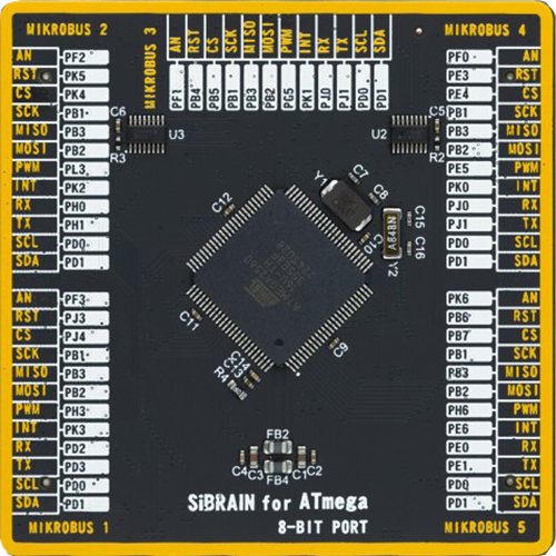
MCU Card / MCU
Type
8th Generation
Architecture
AVR
MCU Memory (KB)
256
Silicon Vendor
Microchip
Pin count
100
RAM (Bytes)
8192
Used MCU Pins
mikroBUS™ mapper
Take a closer look
Click board™ Schematic
Step by step
Project assembly

Start by selecting your development board and Click board™. Begin with the UNI Clicker as your development board.


Software Support
Library Description
This library contains API for IR Grid Click driver.
Key functions:
irgrid_measure- Measures temperature and places it inside internal bufferirgrid_get_temperature- Populates provided buffer with calculated temperaturesirgrid_read_eeprom- Read function using EEPROM slave adress
Open Source
Code example
The complete application code and a ready-to-use project are available through the NECTO Studio Package Manager for direct installation in the NECTO Studio. The application code can also be found on the MIKROE GitHub account.
/*!
 * @file main.c
 * @brief IRGrid Click example
 *
 * # Description
 * IR Grid Click is a thermal imaging sensor. It has an array of 64 very sensitive factory
 * calibrated IR elements (pixels), arranged in 4 rows of 16 pixels, each measuring an
 * object temperature up to 300˚C.
 *
 * The demo application is composed of two sections :
 *
 * ## Application Init
 * Initializes driver init and IR Grid module
 *
 * ## Application Task
 * Reads the temperature of all pixels and creates a pixel temperature matrix that logs
 * on usbuart every half of second
 *
 * @author Mikroe Team
 *
 */

#include "board.h"
#include "log.h"
#include "irgrid.h"

static irgrid_t irgrid;
static irgrid_data_t irgrid_data;
static log_t logger;

static float   ir_tmp[ 64 ];
static uint8_t i;
static uint8_t rc;
static uint8_t cc;

void application_init ( void )
{
    log_cfg_t log_cfg;  /**< Logger config object. */
    irgrid_cfg_t irgrid_cfg;  /**< Click config object. */

    /**
     * Logger initialization.
     * Default baud rate: 115200
     * Default log level: LOG_LEVEL_DEBUG
     * @note If USB_UART_RX and USB_UART_TX
     * are defined as HAL_PIN_NC, you will
     * need to define them manually for log to work.
     * See @b LOG_MAP_USB_UART macro definition for detailed explanation.
     */
    LOG_MAP_USB_UART( log_cfg );
    log_init( &logger, &log_cfg );
    log_info( &logger, " Application Init " );

    // Click initialization.
    irgrid_cfg_setup( &irgrid_cfg );
    IRGRID_MAP_MIKROBUS( irgrid_cfg, MIKROBUS_1 );
    if ( I2C_MASTER_ERROR == irgrid_init( &irgrid, &irgrid_cfg ) )
    {
        log_error( &logger, " Communication init." );
        for ( ; ; );
    }

    irgrid_device_init( &irgrid, &irgrid_data, 16 );

    log_info( &logger, " Application Task " );
}

void application_task ( void )
{
    if ( 1 != irgrid_measure( &irgrid, &irgrid_data ) )
    {
        irgrid_get_temperature( &irgrid_data, &ir_tmp[ 0 ] );
    }

    for ( rc = 0; rc < 4; rc++ )
    {
        for ( cc = 0; cc < 16; cc++ )
        {
            i = ( cc * 4 ) + rc;
            log_printf( &logger, "%.3f    ", ir_tmp[ i ] );
        }
        log_printf( &logger, "\r\n" );
        Delay_ms ( 100 );
    }

    log_printf( &logger, "\r\n" );
    log_printf( &logger, "\r\n" );
    log_printf( &logger, "\r\n" );
    Delay_ms ( 500 );
}

int main ( void )
{
    /* Do not remove this line or clock might not be set correctly. */
    #ifdef PREINIT_SUPPORTED
    preinit();
    #endif

    application_init( );

    for ( ; ; )
    {
        application_task( );
    }

    return 0;
}

// ------------------------------------------------------------------------ END


