Detect the infrared energy of various objects with MLX90640-BAB and STM32F423RH
From cold to bold: The thermal imaging solution you've been waiting for!
Published Sep 21, 2023
Click board™
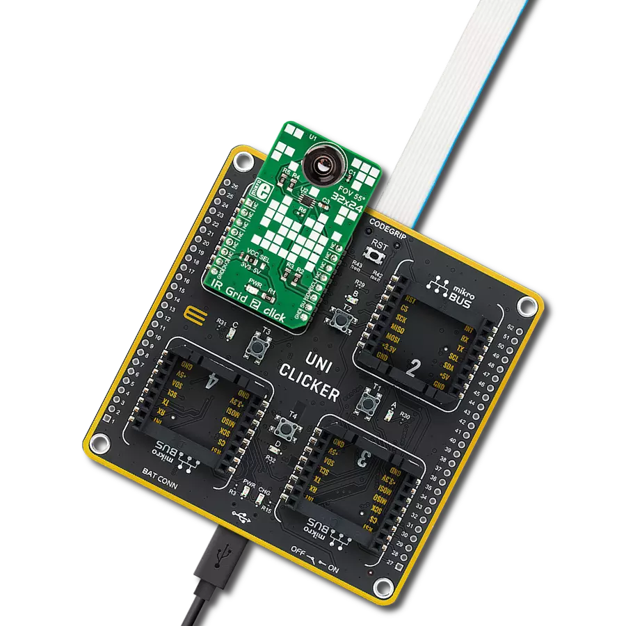
IR Grid 2 click
Dev. board
UNI Clicker
Compiler
NECTO Studio
MCU
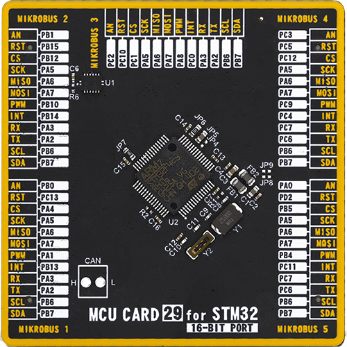
STM32F423RH
Navigate with confidence in diverse environments and conditions, as our thermal imaging technology delivers accurate, real-time temperature data, enabling you to identify issues, monitor trends, and respond swiftly
A
A
Hardware Overview
How does it work?
IR Grid 2 Click is based on the MLX90640, a 32x24 IR array sensor from Melexis. This sensor contains 8 Kbit EEPROM, used to store all the compensation and calibration parameters, along with some editable user parameters, such as the config registers, I2C address and similar. These sensors can measure temperature relative to the cold junction temperature, and for this reason, the MLX90640ESF-BAB IR sensor incorporates a PTAT (Proportional to Absolute Temperature) compensation sensor. The device also contains the power supply voltage measurement feature, allowing power supply monitoring. It is recommended that the supply voltage stay as accurate as possible, which is taken care of if used with the MikroElektronika development systems. The IR sensor array, as well as the PTAT sensor readings, are sampled by the internal Analog to Digital Converter (ADC) and stored to RAM, which can be accessed via the I2C interface. The resolution of the ADC can be programmed between 16 bits and 19bits. The MLX90640ESF-BAB IR sensor used on this Click board™ has a Field of View (FOV) of 55˚x32˚, with the IR sensing elements arranged in a 32x28 grid. Each sensor measures the temperature in its individual FOV, allowing the host MCU to build a thermal image or calculate the temperature at each spot of the viewed scene. The measurement results are stored to RAM. The entire RAM area is divided in two pages, with access patterns controlled by the configuration registers (chess pattern, or
interleaved pattern). The compensation parameters stored in the EEPROM are factory calibrated for chess pattern access, yielding the most accurate results when using this mode. The chess pattern mode is selected by default. The configuration and control registers allow to set the operational parameters of the IR grid sensor. These registers contain bits that control the behavior of the sensor IC: the refresh rate, the ADC resolution, measurement mode (continuous or step mode), sleep mode, I2C mode (FM or FM+), and more. On restart, the data from the corresponding copies of these register locations in EEPROM is mirrored to the operational register locations in RAM, preparing the device to be instantly operated. This allows changing of the default values, since they are actually stored in EEPROM, rather than being hard-coded into the device. Besides the default working parameters, the EEPROM area contains all the compensation parameters for each IR element, necessary for completing the accurate thermal calculations. Those calculations include ambient temperature calculation, pixel offset calculation, pixel to pixel sensitivity difference compensation, object emissivity compensation, and object temperature calculation. The datasheet of the MLX90640ESF-BAB IR sensor contains equations which use these parameters stored in EEPROM. However, this Click board™ is supplied with the library, which contains functions that simplify working with this sensor, saving time. Two modes of operation are available: the device can
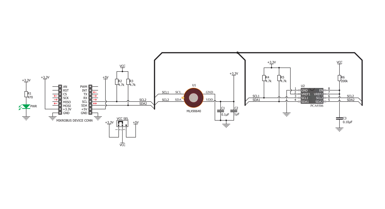
continuously sample data from the IR elements, with the programmed refresh rate (up to 64 frames per second), or it can take one frame, by sampling the selected page. The status byte contains flags that indicate that the reading of a specific page is done. It should be noted that the sensor measures the IR emissivity of an object, so it is to be expected that some materials cannot be accurately measured by this sensor due to their low emissivity, such as the aluminum. To better understand the emissivity property of the materials, a person wearing clothes, can be taken as an example: the measured temperature will reflect the clothes temperature, rather than the body temperature itself, which is known to be about 37 ˚C Care should be taken not to expose the Click board™ to a cold or hot air flow, as it will cause false readings of the real temperature. This sensor requires the temperature across the sensor package to be constant. The MLX90640ESF-BAB IR sensor uses 3.3V for optimal results. While the power for the IR sensor itself is taken from the 3.3V mikroBUS™ rail, in order to support MCUs which use 5V compatible logic levels, the Click board™ comes equipped with PCA9306, a bi-directional I2C level translator IC, produced by Texas Instruments. This allows the logic voltage level to be selected by the SMD jumper labeled as VCC SEL. Besides I2C bus lines, no additional lines of the mikroBUS™ are used. I2C bus lines are routed to the respective pins of the mikroBUS™.


Features overview
Development board
UNI Clicker is a compact development board designed as a complete solution that brings the flexibility of add-on Click boards™ to your favorite microcontroller, making it a perfect starter kit for implementing your ideas. It supports a wide range of microcontrollers, such as different ARM, PIC32, dsPIC, PIC, and AVR from various vendors like Microchip, ST, NXP, and TI (regardless of their number of pins), four mikroBUS™ sockets for Click board™ connectivity, a USB connector, LED indicators, buttons, a debugger/programmer connector, and two 26-pin headers for interfacing with external electronics. Thanks to innovative manufacturing technology, it allows you to build
gadgets with unique functionalities and features quickly. Each part of the UNI Clicker development kit contains the components necessary for the most efficient operation of the same board. In addition to the possibility of choosing the UNI Clicker programming method, using a third-party programmer or CODEGRIP/mikroProg connected to onboard JTAG/SWD header, the UNI Clicker board also includes a clean and regulated power supply module for the development kit. It provides two ways of board-powering; through the USB Type-C (USB-C) connector, where onboard voltage regulators provide the appropriate voltage levels to each component on the board, or using a Li-Po/Li
Ion battery via an onboard battery connector. All communication methods that mikroBUS™ itself supports are on this board (plus USB HOST/DEVICE), including the well-established mikroBUS™ socket, a standardized socket for the MCU card (SiBRAIN standard), and several user-configurable buttons and LED indicators. UNI Clicker is an integral part of the Mikroe ecosystem, allowing you to create a new application in minutes. Natively supported by Mikroe software tools, it covers many aspects of prototyping thanks to a considerable number of different Click boards™ (over a thousand boards), the number of which is growing every day.

Microcontroller Overview
MCU Card / MCU
Type
8th Generation
Architecture
ARM Cortex-M4
MCU Memory (KB)
1536
Silicon Vendor
STMicroelectronics
Pin count
64
RAM (Bytes)
327680
Used MCU Pins
mikroBUS™ mapper
Take a closer look
Click board™ Schematic
Step by step
Project assembly

Start by selecting your development board and Click board™. Begin with the UNI Clicker as your development board.


Software Support
Library Description
This library contains API for IR Grid 2 Click driver.
Key functions:
irgrid2_generic_write- This function reads a desired number of data bytes starting from the selected register by using I2C serial interfaceirgrid2_get_frame_data- This function is used for getting frame datairgrid2_get_pixel_temperature- This function is used for getting pixels temperature
Open Source
Code example
The complete application code and a ready-to-use project are available through the NECTO Studio Package Manager for direct installation in the NECTO Studio. The application code can also be found on the MIKROE GitHub account.
/*!
 * @file main.c
 * @brief IRGrid2 Click example
 *
 * # Description
 * The demo application displays a reading of ambient temperature and
 * a 32x24 pixel object temperature matrix.
 *
 * The demo application is composed of two sections :
 *
 * ## Application Init
 * Configures the Click and log objects and sets the Click default configuration.
 *
 * ## Application Task
 * Reads the temperature of all pixels every 500ms
 * and displays it on USB UART in a form of a 32x24 matrix.
 *
 * @author Stefan Ilic
 *
 */

#include "board.h"
#include "log.h"
#include "irgrid2.h"

static irgrid2_t irgrid2;
static log_t logger;

void application_init ( void ) {
    log_cfg_t log_cfg;  /**< Logger config object. */
    irgrid2_cfg_t irgrid2_cfg;  /**< Click config object. */

    /**
     * Logger initialization.
     * Default baud rate: 115200
     * Default log level: LOG_LEVEL_DEBUG
     * @note If USB_UART_RX and USB_UART_TX
     * are defined as HAL_PIN_NC, you will
     * need to define them manually for log to work.
     * See @b LOG_MAP_USB_UART macro definition for detailed explanation.
     */
    LOG_MAP_USB_UART( log_cfg );
    log_init( &logger, &log_cfg );
    log_info( &logger, "---- Application Init ----" );

    // Click initialization.
    irgrid2_cfg_setup( &irgrid2_cfg );
    IRGRID2_MAP_MIKROBUS( irgrid2_cfg, MIKROBUS_1 );
    err_t init_flag = irgrid2_init( &irgrid2, &irgrid2_cfg );
    if ( I2C_MASTER_ERROR == init_flag ) {
        log_error( &logger, " Application Init Error. " );
        log_info( &logger, " Please, run program again... " );

        for ( ; ; );
    }

    irgrid2_default_cfg ( &irgrid2 );
    Delay_ms ( 1000 );
    log_info( &logger, "---- Start measurement ----" );
}

void application_task ( void ) {
    float px_matrix[ 768 ];
    float temp_ambient;

    irgrid2_get_pixel_temperature( &irgrid2, &temp_ambient, px_matrix );

    log_printf( &logger, "\r\n>> Pixel temperature matrix 32x24 <<\r\n" );
    for ( uint16_t cnt = 1 ; cnt < 769 ; cnt++) {
        log_printf( &logger, "%.2f", px_matrix[ cnt - 1 ] );
        if ( ( ( cnt % 32 ) == 0 ) ) {
            log_printf( &logger, "\r\n" );
        } else {
            log_printf( &logger, " | " );
        }
    }
    log_printf( &logger, "\r\n** Ambient (sensor) temperature is %.2f Celsius\r\n", temp_ambient );
    Delay_ms ( 500 );
}

int main ( void )
{
    /* Do not remove this line or clock might not be set correctly. */
    #ifdef PREINIT_SUPPORTED
    preinit();
    #endif

    application_init( );

    for ( ; ; )
    {
        application_task( );
    }

    return 0;
}

// ------------------------------------------------------------------------ END


