Design a portable color analyzer with CLS-16D24-44-DF8/TR8 and PIC18F57Q43
Sensing the rainbow!

Published Feb 13, 2024
Click board™
Color 15 Click
Dev. board
Curiosity Nano with PIC18F57Q43
Compiler
NECTO Studio
MCU
PIC18F57Q43
Get the colors you need with our highly sensitive and accurate color-sensing solution
A
A
Hardware Overview
How does it work?
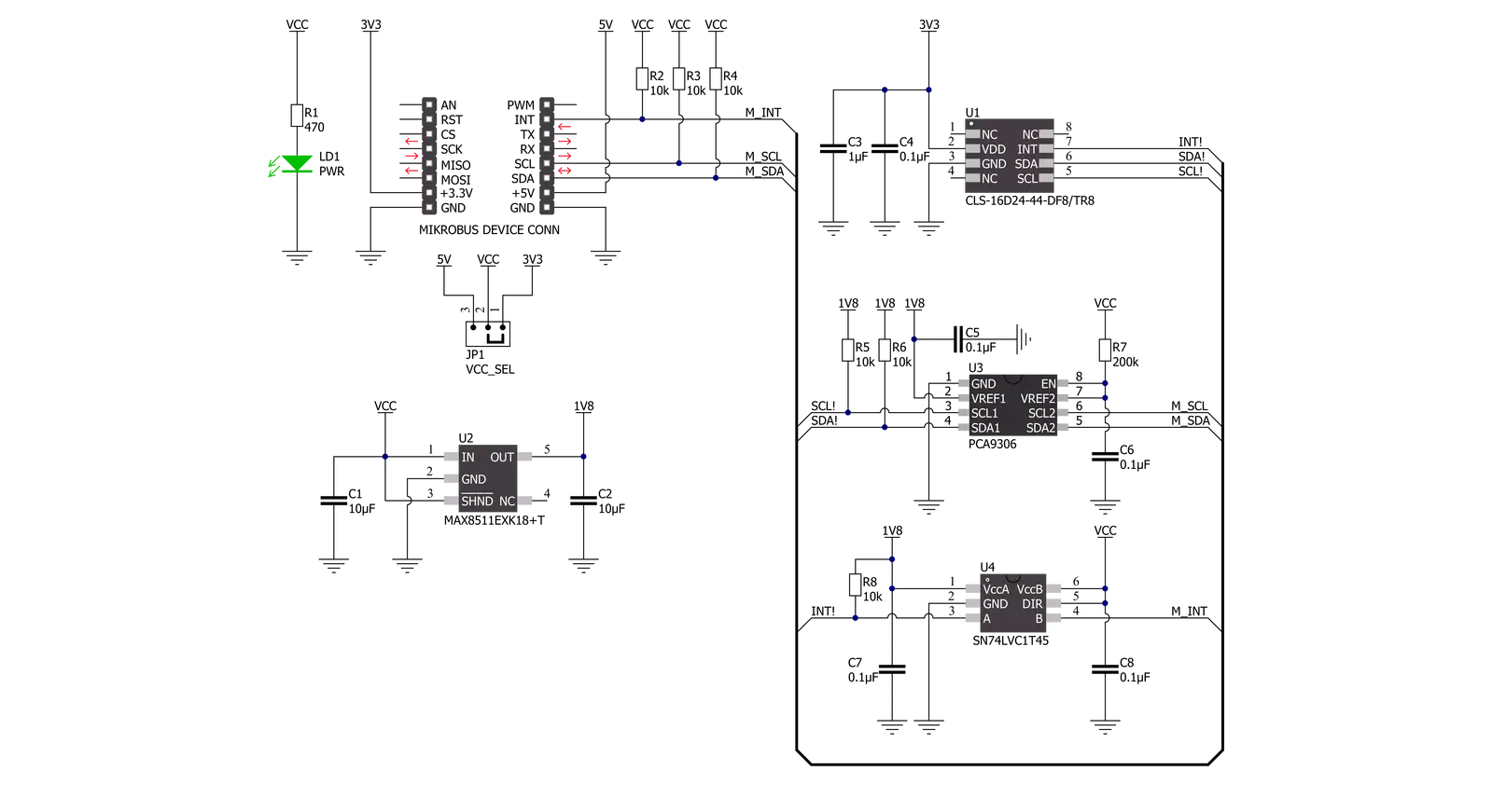
Color 15 Click is based on the CLS-16D24-44-DF8/TR8, a digital I2C compatible interface color light sensor from Everlight Electronics. It supports parallel output for Red, Green, Blue, White, and Infrared light (R, G, B, W, IR) and converts them to a 16-bit digital value (0-65535). This sensor is characterized by high resolution designed to reject IR in light sources allowing the device to operate in environments from sunlight to dark rooms, with a maximum detection lux of 204.679lux. Besides, an integrated ADC rejects 50Hz and 60Hz flickers caused by artificial light sources. It also has stable performance over a wide temperature range of -40°C to 65°C, suitable for measuring the present color light.
The CLS-16D24-44-DF8/TR8 does not require a specific Power-Up sequence but requires a voltage of 1.8V for its interface and logic part to work correctly. Therefore, a small regulating LDO, the MAX8511, provides a 1.8V out of selected mikroBUS™ power rail. Color 15 Click communicates with MCU using the standard I2C 2-Wire interface with a maximum clock frequency of 400kHz, fully adjustable through software registers. Since the sensor for operation requires a power supply of 3.3V, this Click board™ also features the PCA9306 and SN74LVC1T45 voltage-level translators. The I2C interface bus lines are routed to the voltage-level translators allowing this Click board™ to work with both 3.3V and 5V MCUs properly.
Also, it uses an interrupt pin, the INT pin of the mikroBUS™ socket, used when an interrupt occurs to alert the system when the color result crosses upper or lower threshold settings. This Click board™ can operate with either 3.3V or 5V logic voltage levels selected via the VCC SEL jumper. This way, both 3.3V and 5V capable MCUs can use the communication lines properly. However, the Click board™ comes equipped with a library containing easy-to-use functions and an example code that can be used, as a reference, for further development.


Features overview
Development board
PIC18F57Q43 Curiosity Nano evaluation kit is a cutting-edge hardware platform designed to evaluate microcontrollers within the PIC18-Q43 family. Central to its design is the inclusion of the powerful PIC18F57Q43 microcontroller (MCU), offering advanced functionalities and robust performance. Key features of this evaluation kit include a yellow user LED and a responsive
mechanical user switch, providing seamless interaction and testing. The provision for a 32.768kHz crystal footprint ensures precision timing capabilities. With an onboard debugger boasting a green power and status LED, programming and debugging become intuitive and efficient. Further enhancing its utility is the Virtual serial port (CDC) and a debug GPIO channel (DGI
GPIO), offering extensive connectivity options. Powered via USB, this kit boasts an adjustable target voltage feature facilitated by the MIC5353 LDO regulator, ensuring stable operation with an output voltage ranging from 1.8V to 5.1V, with a maximum output current of 500mA, subject to ambient temperature and voltage constraints.

Microcontroller Overview
MCU Card / MCU

Architecture
PIC
MCU Memory (KB)
128
Silicon Vendor
Microchip
Pin count
48
RAM (Bytes)
8196
You complete me!
Accessories
Curiosity Nano Base for Click boards is a versatile hardware extension platform created to streamline the integration between Curiosity Nano kits and extension boards, tailored explicitly for the mikroBUS™-standardized Click boards and Xplained Pro extension boards. This innovative base board (shield) offers seamless connectivity and expansion possibilities, simplifying experimentation and development. Key features include USB power compatibility from the Curiosity Nano kit, alongside an alternative external power input option for enhanced flexibility. The onboard Li-Ion/LiPo charger and management circuit ensure smooth operation for battery-powered applications, simplifying usage and management. Moreover, the base incorporates a fixed 3.3V PSU dedicated to target and mikroBUS™ power rails, alongside a fixed 5.0V boost converter catering to 5V power rails of mikroBUS™ sockets, providing stable power delivery for various connected devices.

Used MCU Pins
mikroBUS™ mapper
Take a closer look
Click board™ Schematic
Step by step
Project assembly

Start by selecting your development board and Click board™. Begin with the Curiosity Nano with PIC18F57Q43 as your development board.


Track your results in real time
Application Output
1. Application Output - In Debug mode, the 'Application Output' window enables real-time data monitoring, offering direct insight into execution results. Ensure proper data display by configuring the environment correctly using the provided tutorial.

2. UART Terminal - Use the UART Terminal to monitor data transmission via a USB to UART converter, allowing direct communication between the Click board™ and your development system. Configure the baud rate and other serial settings according to your project's requirements to ensure proper functionality. For step-by-step setup instructions, refer to the provided tutorial.

3. Plot Output - The Plot feature offers a powerful way to visualize real-time sensor data, enabling trend analysis, debugging, and comparison of multiple data points. To set it up correctly, follow the provided tutorial, which includes a step-by-step example of using the Plot feature to display Click board™ readings. To use the Plot feature in your code, use the function: plot(*insert_graph_name*, variable_name);. This is a general format, and it is up to the user to replace 'insert_graph_name' with the actual graph name and 'variable_name' with the parameter to be displayed.

Software Support
Library Description
This library contains API for Color 15 Click driver.
Key functions:
color15_get_dataThis function reads data from 5 channels (Red, Green, Blue, White, IR).color15_rgbw_to_hslThis function converts RGBW (red, green, blue, white) to HSL (hue, saturation, lightness) color value.color15_get_colorThis function returns the color name flag from the input HSL color.
Open Source
Code example
The complete application code and a ready-to-use project are available through the NECTO Studio Package Manager for direct installation in the NECTO Studio. The application code can also be found on the MIKROE GitHub account.
/*!
 * @file main.c
 * @brief Color15 Click example
 *
 * # Description
 * This example demonstrates the use of Color 15 Click board by reading data
 * from 5 channels and converting them to HSL color and displaying those data as
 * well as the detected color name on the USB UART.
 *
 * The demo application is composed of two sections :
 *
 * ## Application Init
 * Initializes the driver and performs the Click default configuration.
 *
 * ## Application Task
 * Waits for the data ready interrupt, then reads the values of all channels and converts
 * them to HSL color and displays those data as well as the detected color name on the USB UART
 * every 500ms approximately.
 *
 * @author Stefan Filipovic
 *
 */

#include "board.h"
#include "log.h"
#include "color15.h"

static color15_t color15;
static log_t logger;

void application_init ( void )
{
    log_cfg_t log_cfg;  /**< Logger config object. */
    color15_cfg_t color15_cfg;  /**< Click config object. */

    /**
     * Logger initialization.
     * Default baud rate: 115200
     * Default log level: LOG_LEVEL_DEBUG
     * @note If USB_UART_RX and USB_UART_TX
     * are defined as HAL_PIN_NC, you will
     * need to define them manually for log to work.
     * See @b LOG_MAP_USB_UART macro definition for detailed explanation.
     */
    LOG_MAP_USB_UART( log_cfg );
    log_init( &logger, &log_cfg );
    log_info( &logger, " Application Init " );

    // Click initialization.
    color15_cfg_setup( &color15_cfg );
    COLOR15_MAP_MIKROBUS( color15_cfg, MIKROBUS_1 );
    if ( I2C_MASTER_ERROR == color15_init( &color15, &color15_cfg ) )
    {
        log_error( &logger, " Communication init." );
        for ( ; ; );
    }

    if ( COLOR15_ERROR == color15_default_cfg ( &color15 ) )
    {
        log_error( &logger, " Default configuration." );
        for ( ; ; );
    }

    log_info( &logger, " Application Task " );
}

void application_task ( void )
{
    // Wait for the data ready interrupt indication
    while ( color15_get_int_pin ( &color15 ) );

    color15_channels_t channels;
    if ( ( COLOR15_OK == color15_clear_interrupt ( &color15 ) ) &&
         ( COLOR15_OK == color15_get_data ( &color15, &channels ) ) )
    {
        color15_hsl_t hsl;
        color15_rgbw_to_hsl ( &color15, &channels, &hsl );
        log_printf ( &logger, "\r\n Hue: %.1f deg\r\n", hsl.hue );
        log_printf ( &logger, " Saturation: %.1f %%\r\n", hsl.saturation );
        log_printf ( &logger, " Lightness: %.1f %%\r\n", hsl.lightness );
        switch ( color15_get_color ( &hsl ) )
        {
            case COLOR15_RED_COLOR:
            {
                log_printf( &logger, " Color: RED\r\n" );
                break;
            }
            case COLOR15_YELLOW_COLOR:
            {
                log_printf( &logger, " Color: YELLOW\r\n" );
                break;
            }
            case COLOR15_GREEN_COLOR:
            {
                log_printf( &logger, " Color: GREEN\r\n" );
                break;
            }
            case COLOR15_CYAN_COLOR:
            {
                log_printf( &logger, " Color: CYAN\r\n" );
                break;
            }
            case COLOR15_BLUE_COLOR:
            {
                log_printf( &logger, " Color: BLUE\r\n" );
                break;
            }
            case COLOR15_MAGENTA_COLOR:
            {
                log_printf( &logger, " Color: MAGENTA\r\n" );
                break;
            }
            case COLOR15_WHITE_COLOR:
            {
                log_printf( &logger, " Color: WHITE\r\n" );
                break;
            }
            case COLOR15_BLACK_COLOR:
            {
                log_printf( &logger, " Color: BLACK\r\n" );
                break;
            }
            default:
            {
                log_printf( &logger, " Color: UNKNOWN\r\n" );
                break;
            }
        }
    }
}

int main ( void )
{
    /* Do not remove this line or clock might not be set correctly. */
    #ifdef PREINIT_SUPPORTED
    preinit();
    #endif

    application_init( );

    for ( ; ; )
    {
        application_task( );
    }

    return 0;
}

// ------------------------------------------------------------------------ END
Additional Support
Resources
Category:Optical


