Comprehensive heart monitoring based on SFH7050 and dsPIC33EP512MU814
Your heart, in real-time

Published Jul 01, 2023
Click board™
Heart Rate 3 Click
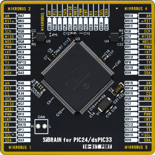
Dev. board
UNI Clicker
Compiler
NECTO Studio
MCU
dsPIC33EP512MU814
Develop algorithms for pulse oximetry and heart rate readings through the tip of a finger
A
A
Hardware Overview
How does it work?
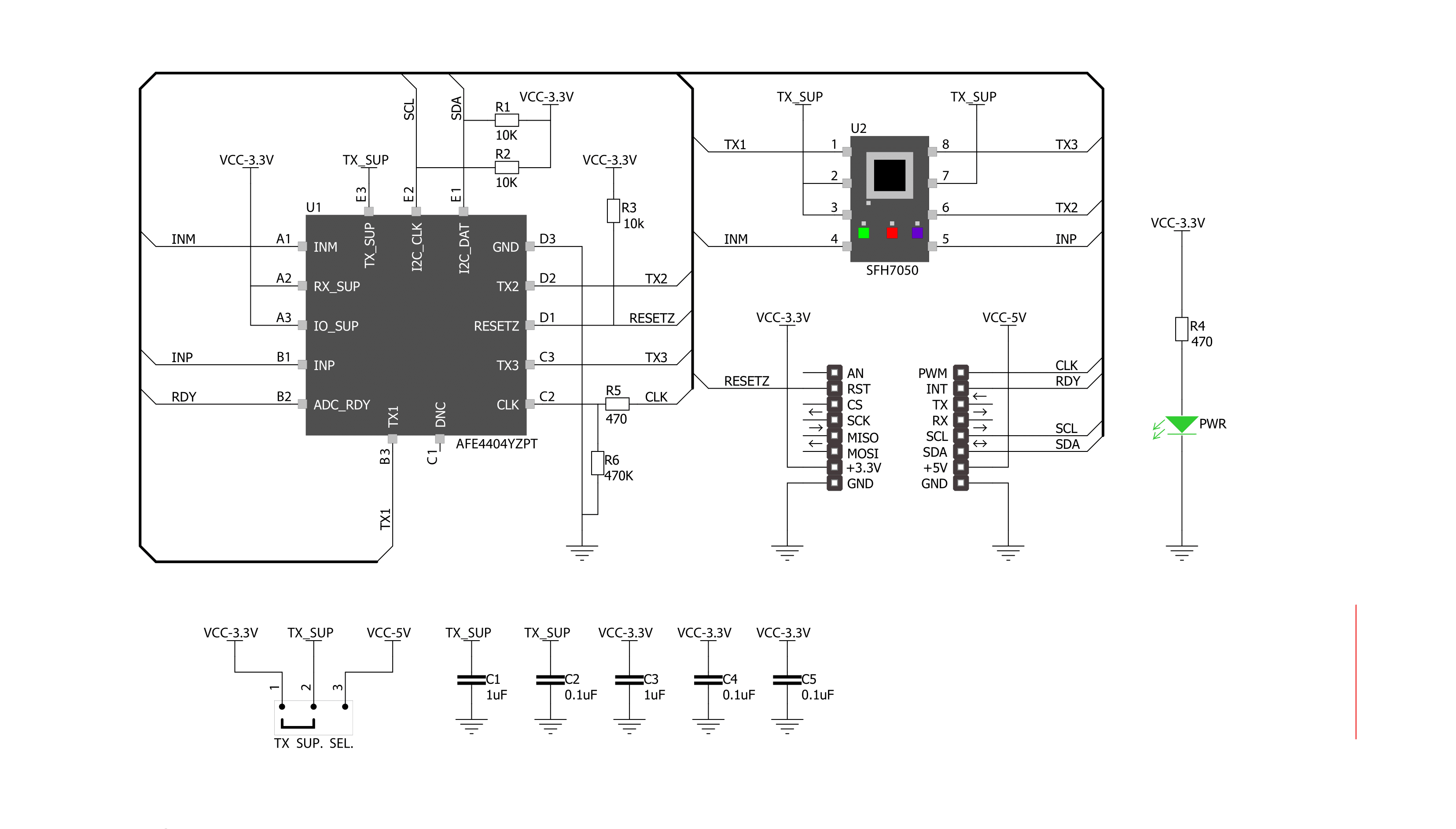
Heart Rate 3 Click is based on the SFH7050, a pulse oximetry and heart rate sensor from ams OSRAM. This multi-chip package consists of three emitters and one detector, with a light barrier to block crosstalk between the LEDs and the detector. These emitters are green, red, and infrared LEDs pointed toward the measuring objects (human skin, finger). The green LED is most commonly used to measure the dilatation of the blood vessels. The red and the infrared LED light are absorbed differently by oxygen-rich and oxygen-poor blood; therefore, the SFH7050 consists of both of them. The peak wavelength differs from each LED, but the half angle is the same for all three LEDs, ± 60°. As a detector, separated by a block barrier, the photodiode detects the intensity of light returned. As mentioned, this Click board™ uses three LEDs and a photodiode to detect the intensity of light returned, and besides them, it also features the AFE4404, an integrated AFE for optical heart-rate monitoring and bio-sensing from Texas Instruments. The AFE4404 includes a 6-bit
programmable LED current for all three LEDs and individual DC offset subtraction DAC at TIA (Transimpedance Amplifier) input for each LED and ambient phase, allowing to increase sensor's accuracy and remove the noise from the signal. There is also a way to average the 24-bit output from the photodiode before sending it to the BPM algorithm for better noise cancellation. To communicate to the host MCU, the Heart Rate 3 Click uses the I2C interface of the AFE4404 over the mikroBUS™ socket. Every time all three LEDs have finished sampling and converting, the interrupt is triggered over the RDY pin, thus saving the host MCU from constantly polling the sensor for data. This pin is set to a high logic level when the PRF (a pulse repetition frequency) cycle ends, allowing four output data register to be read. The PRF can vary between 10 to 1000 samples per second. The clock input can be selected over the CLK pin, as the AFE4404 can be clocked both internally and externally. The input clock can go up to 60MHz, but the internal divider of the IC has to be set so that the clock stays within the range
from 4MHz to 6MHz. When driven by the internal clock, the device runs at 4MHz. By default, the external clock input is selected. The users can choose one of the clock options over the R5 and R6 resistors (R5 for external clock mode and R6 for internal oscillator mode). After the Power-on sequence, the AFE requires a reset. The RST pin of the mikroBUS™ socket allows the AFE to be reset by the host MCU. Pulling this pin to a low logic state for more than 200µs will put the device into the Power Down mode. The AFE can also be reset by setting a bit in the appropriate register via the I2C interface. This Click board™ can only be operated with a 3.3V logic voltage level. The board must perform appropriate logic voltage level conversion before using MCUs with different logic levels. However, the Click board™ comes equipped with a library containing functions and an example code that can be used, as a reference, for further development. Although the Heart Rate 3 Click is a 3.3V logic level only, the onboard LED SUP jumper allows you to set the voltage for driving the SFH7050 LEDs at either 3.3V or 5V.


Features overview
Development board
UNI Clicker is a compact development board designed as a complete solution that brings the flexibility of add-on Click boards™ to your favorite microcontroller, making it a perfect starter kit for implementing your ideas. It supports a wide range of microcontrollers, such as different ARM, PIC32, dsPIC, PIC, and AVR from various vendors like Microchip, ST, NXP, and TI (regardless of their number of pins), four mikroBUS™ sockets for Click board™ connectivity, a USB connector, LED indicators, buttons, a debugger/programmer connector, and two 26-pin headers for interfacing with external electronics. Thanks to innovative manufacturing technology, it allows you to build
gadgets with unique functionalities and features quickly. Each part of the UNI Clicker development kit contains the components necessary for the most efficient operation of the same board. In addition to the possibility of choosing the UNI Clicker programming method, using a third-party programmer or CODEGRIP/mikroProg connected to onboard JTAG/SWD header, the UNI Clicker board also includes a clean and regulated power supply module for the development kit. It provides two ways of board-powering; through the USB Type-C (USB-C) connector, where onboard voltage regulators provide the appropriate voltage levels to each component on the board, or using a Li-Po/Li
Ion battery via an onboard battery connector. All communication methods that mikroBUS™ itself supports are on this board (plus USB HOST/DEVICE), including the well-established mikroBUS™ socket, a standardized socket for the MCU card (SiBRAIN standard), and several user-configurable buttons and LED indicators. UNI Clicker is an integral part of the Mikroe ecosystem, allowing you to create a new application in minutes. Natively supported by Mikroe software tools, it covers many aspects of prototyping thanks to a considerable number of different Click boards™ (over a thousand boards), the number of which is growing every day.

Microcontroller Overview
MCU Card / MCU
Type
8th Generation
Architecture
dsPIC
MCU Memory (KB)
512
Silicon Vendor
Microchip
Pin count
144
RAM (Bytes)
53248
Used MCU Pins
mikroBUS™ mapper
Take a closer look
Click board™ Schematic
Step by step
Project assembly

Start by selecting your development board and Click board™. Begin with the UNI Clicker as your development board.


Software Support
Library Description
This library contains API for Heart Rate 3 Click driver.
Key functions:
heartrate3_check_data_ready- Function is used to check data ready flagheartrate3_write_data- Function is used to write 32-bit data into registerheartrate3_read_24bit- Function is used to read 24-bit value from register
Open Source
Code example
The complete application code and a ready-to-use project are available through the NECTO Studio Package Manager for direct installation in the NECTO Studio. The application code can also be found on the MIKROE GitHub account.
/*!
 * \file
 * \brief HeartRate3 Click example
 *
 * # Description
 * The demo application shows reflected red, green and ir values.
 *
 * The demo application is composed of two sections :
 *
 * ## Application Init
 * Initalizes Click driver, resets the device, applies default settings
 * and makes an initial log.
 *
 * ## Application Task
 * This example demonstrates the use of Heart rate 3 board. It is set in default
 * mode, and reads reflected red, green and ir values and displays the results
 * on USART terminal.
 *
 * @note
 * We recommend using the SerialPlot tool for data visualizing.
 *
 * \author Jovan Stajkovic
 *
 */
// ------------------------------------------------------------------- INCLUDES

#include "board.h"
#include "log.h"
#include "heartrate3.h"

// ------------------------------------------------------------------ VARIABLES

static heartrate3_t heartrate3;
static log_t logger;

static uint32_t led_2;
static uint32_t aled_2;
static uint32_t led_1;
static uint32_t aled_1;
static uint32_t led_2_aled_2;
static uint32_t led_1_aled_1;

// ------------------------------------------------------ APPLICATION FUNCTIONS

void application_init ( void )
{
    log_cfg_t log_cfg;
    heartrate3_cfg_t heartrate3_cfg;

    /**
     * Logger initialization.
     * Default baud rate: 115200
     * Default log level: LOG_LEVEL_DEBUG
     * @note If USB_UART_RX and USB_UART_TX
     * are defined as HAL_PIN_NC, you will
     * need to define them manually for log to work.
     * See @b LOG_MAP_USB_UART macro definition for detailed explanation.
     */
    LOG_MAP_USB_UART( log_cfg );
    log_init( &logger, &log_cfg );
    log_info( &logger, "---- Application Init ----" );

    //  Click initialization.
    heartrate3_cfg_setup( &heartrate3_cfg );
    HEARTRATE3_MAP_MIKROBUS( heartrate3_cfg, MIKROBUS_1 );
    if ( I2C_MASTER_ERROR == heartrate3_init( &heartrate3, &heartrate3_cfg ) )
    {
        log_error( &logger, " Communication init." );
        for ( ; ; );
    }

    log_printf( &logger, "----------------------\r\n" );
    log_printf( &logger, "  Heart rate 3 Click  \r\n" );
    log_printf( &logger, "----------------------\r\n" );

    if ( HEARTRATE3_ERROR == heartrate3_default_cfg ( &heartrate3 ) )
    {
        log_error( &logger, " Default configuration." );
        for ( ; ; );
    }

    log_printf( &logger, "     Initialised!     \r\n" );
    log_printf( &logger, "----------------------\r\n" );
    log_info( &logger, " Application Task " );
    Delay_ms ( 100 );
}

void application_task ( void )
{
    err_t error_flag = HEARTRATE3_OK;
    if ( heartrate3_check_data_ready ( &heartrate3 ) )
    {
        error_flag |= heartrate3_read_24bit( &heartrate3, HEARTRATE3_REG_LED2VAL, &led_2 );
        error_flag |= heartrate3_read_24bit( &heartrate3, HEARTRATE3_REG_ALED2VAL, &aled_2 );
        error_flag |= heartrate3_read_24bit( &heartrate3, HEARTRATE3_REG_LED1VAL, &led_1 );
        error_flag |= heartrate3_read_24bit( &heartrate3, HEARTRATE3_REG_ALED1VAL, &aled_1 );
        error_flag |= heartrate3_read_24bit( &heartrate3, HEARTRATE3_REG_LED2_ALED2VAL, &led_2_aled_2 );
        error_flag |= heartrate3_read_24bit( &heartrate3, HEARTRATE3_REG_LED1_ALED1VAL, &led_1_aled_1 );
        if ( HEARTRATE3_OK == error_flag )
        {
            log_printf( &logger, "%lu;%lu;%lu;%lu;%lu;%lu;\r\n",
                        led_2, aled_2, led_1, aled_1, led_2_aled_2, led_1_aled_1 );
        }
    }
}

int main ( void )
{
    /* Do not remove this line or clock might not be set correctly. */
    #ifdef PREINIT_SUPPORTED
    preinit();
    #endif

    application_init( );

    for ( ; ; )
    {
        application_task( );
    }

    return 0;
}


// ------------------------------------------------------------------------ END


