Simplify your connections and unlock limitless creative potential with STM32F767BI
mikroBUS™ signals at your fingertips
Published Nov 09, 2023
Click board™
Terminal 2 Click
Dev. board
Clicker 4 for STM32
Compiler
NECTO Studio
MCU
STM32F767BI
Get easy access to mikroBUS™ signals, allowing you to tinker and experiment with your projects effortlessly.
A
A
Hardware Overview
How does it work?
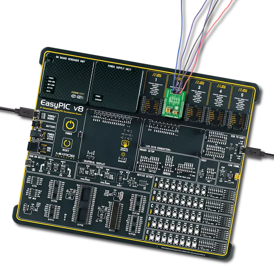
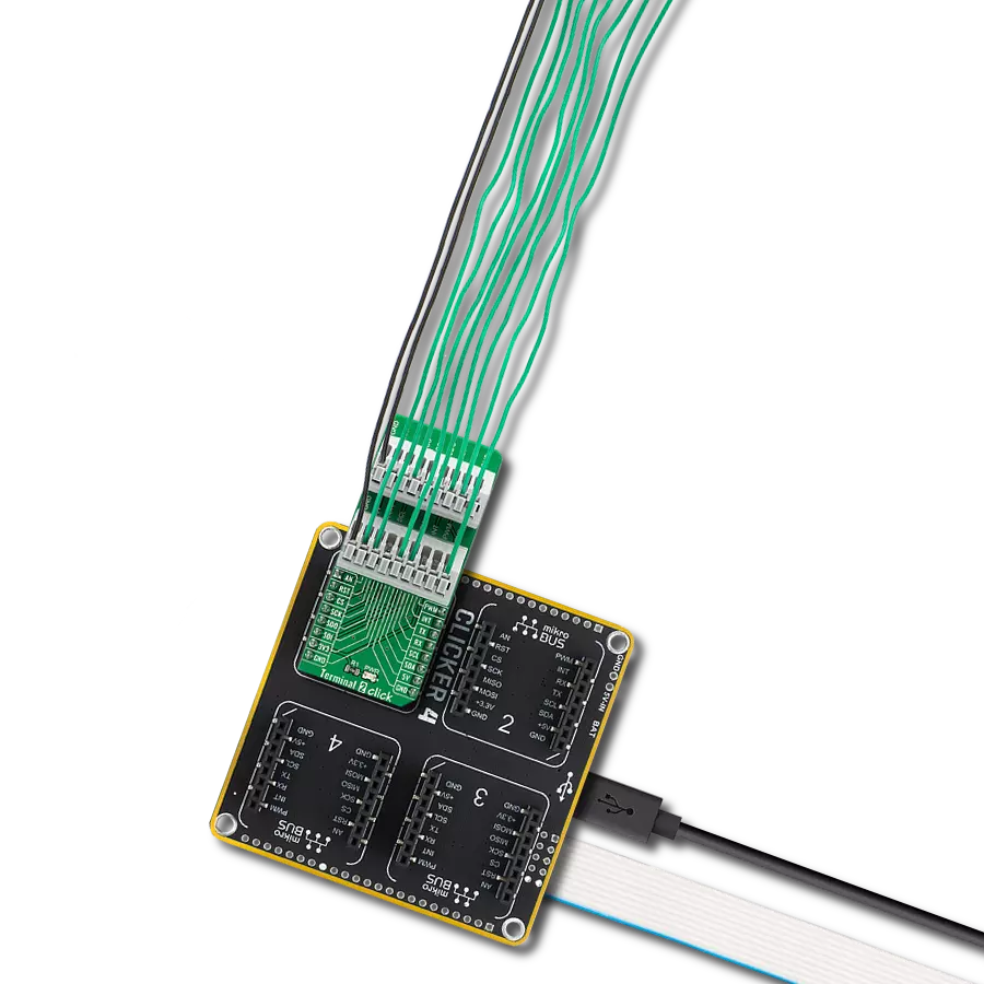
Terminal 2 Click is an adapter Click board™ used as a mikroBUS™ socket expansion board. This Click board™ provides an easy and elegant solution for adding the external connection capability to the Click board™ and can be connected to the mikroBUS™ socket like any other Click board™. On the central area of the Terminal 2 Click, two 9-position 2.54mm pitch terminal blocks are placed. Each of the terminal pins corresponds to a pin on the mikroBUS™ socket. Thanks to these terminals, the connection
with the Click board™ remains firm and stable, retaining a perfect connection quality at all times. Lines of the mikroBUS™ socket to which Terminal 2 Click is attached are shared through the onboard connectors, which mirror the connected mikroBUS™ socket pins. Therefore, care should be taken when working with the Terminal 2 Click and connecting an external device to it because the same pins on the mikroBUS™ are shared, either for the communication (SPI, UART, I2C) or for some other purpose (RST, INT, or other pins used as
GPIO). This Click board™ can operate with both 3.3V and 5V logic voltage levels. This way, it is allowed for both 3.3V and 5V capable MCUs to use the communication lines properly. A green LED visually detects the presence of an active power supply labeled as PWR. Also, this Click board™ comes equipped with a library containing easy-to-use functions and an example code that can be used as a reference for further development.

Features overview
Development board
Clicker 4 for STM32 is a compact development board designed as a complete solution that brings the flexibility of add-on Click boards™ to your favorite microcontroller, making it a perfect starter kit for implementing your ideas. It comes with an onboard 32-bit ARM Cortex-M4 microcontroller, the STM32F767BI from STMicroelectronics, four mikroBUS™ sockets for Click board™ connectivity, a USB connector, LED indicators, buttons, a debugger/programmer connector, two 23-pin headers for interfacing with external electronics, and more. Thanks to innovative manufacturing technology, it allows you to build gadgets with
unique functionalities and features quickly. Each part of the Clicker 4 for STM32 development kit contains the components necessary for the most efficient operation of the same board. In addition to the possibility of choosing the Clicker 4 for STM32 programming method, using an external CODEGRIP or mikroProg programmer connected to the onboard JTAG/SWD header, the Clicker 4 board also includes a clean and regulated power supply block. It provides several ways of board-powering; through the USB Type-C (USB-C) connector using a power supply delivered by the USB HOST (i.e., personal computer), USB wall
adapter, or a Li-Po/Li-Ion battery via an onboard battery connector. All communication methods that mikroBUS™ itself supports are on this board (plus USB-DEVICE), including the well-established mikroBUS™ socket, several user-configurable buttons, and LED indicators. Clicker 4 for STM32 is an integral part of the Mikroe ecosystem, allowing you to create a new application in minutes. Natively supported by Mikroe software tools, it covers many aspects of prototyping thanks to a considerable number of different Click boards™ (over a thousand boards), the number of which is growing every day.

Microcontroller Overview
MCU Card / MCU
Architecture
ARM Cortex-M7
MCU Memory (KB)
2048
Silicon Vendor
STMicroelectronics
Pin count
208
RAM (Bytes)
524288
Used MCU Pins
mikroBUS™ mapper
Take a closer look
Click board™ Schematic

Step by step
Project assembly

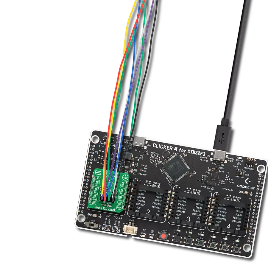
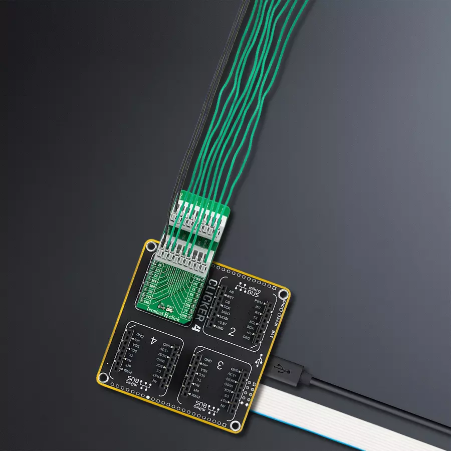
Start by selecting your development board and Click board™. Begin with the Clicker 4 for STM32 as your development board.


Track your results in real time
Application Output
1. Application Output - In Debug mode, the 'Application Output' window enables real-time data monitoring, offering direct insight into execution results. Ensure proper data display by configuring the environment correctly using the provided tutorial.

2. UART Terminal - Use the UART Terminal to monitor data transmission via a USB to UART converter, allowing direct communication between the Click board™ and your development system. Configure the baud rate and other serial settings according to your project's requirements to ensure proper functionality. For step-by-step setup instructions, refer to the provided tutorial.

3. Plot Output - The Plot feature offers a powerful way to visualize real-time sensor data, enabling trend analysis, debugging, and comparison of multiple data points. To set it up correctly, follow the provided tutorial, which includes a step-by-step example of using the Plot feature to display Click board™ readings. To use the Plot feature in your code, use the function: plot(*insert_graph_name*, variable_name);. This is a general format, and it is up to the user to replace 'insert_graph_name' with the actual graph name and 'variable_name' with the parameter to be displayed.

Software Support
Library Description
This library contains API for Terminal 2 Click driver.
Key functions:
terminal2_set_all_pins_high- This function sets all terminal pins to high logic level.terminal2_set_all_pins_low- This function sets all terminal pins to low logic level.terminal2_toggle_pin- This function toggles the specified pin logic level.
Open Source
Code example
The complete application code and a ready-to-use project are available through the NECTO Studio Package Manager for direct installation in the NECTO Studio. The application code can also be found on the MIKROE GitHub account.
/*!
 * @file main.c
 * @brief Terminal 2 Click Example.
 *
 * # Description
 * This example demonstates the use of Terminal 2 Click board by toggling all its pins.
 *
 * The demo application is composed of two sections :
 *
 * ## Application Init
 * Initializes the driver and logger and sets all pins to low logic state.
 *
 * ## Application Task
 * Toggles all pins from mikroBUS one by one in the span of 1 second between each pin toggle.
 *
 * @author Stefan Filipovic
 *
 */

#include "board.h"
#include "log.h"
#include "terminal2.h"

static terminal2_t terminal2;   /**< Terminal 2 Click driver object. */
static log_t logger;    /**< Logger object. */

void application_init ( void )
{
    log_cfg_t log_cfg;  /**< Logger config object. */
    terminal2_cfg_t terminal2_cfg;  /**< Click config object. */

    /**
     * Logger initialization.
     * Default baud rate: 115200
     * Default log level: LOG_LEVEL_DEBUG
     * @note If USB_UART_RX and USB_UART_TX
     * are defined as HAL_PIN_NC, you will
     * need to define them manually for log to work.
     * See @b LOG_MAP_USB_UART macro definition for detailed explanation.
     */
    LOG_MAP_USB_UART( log_cfg );
    log_init( &logger, &log_cfg );
    log_info( &logger, " Application Init " );

    // Click initialization.
    terminal2_cfg_setup( &terminal2_cfg );
    TERMINAL2_MAP_MIKROBUS( terminal2_cfg, MIKROBUS_1 );
    if ( DIGITAL_OUT_UNSUPPORTED_PIN == terminal2_init( &terminal2, &terminal2_cfg ) )
    {
        log_error( &logger, " Communication init." );
        for ( ; ; );
    }
    terminal2_set_all_pins_low ( &terminal2 );

    log_info( &logger, " Application Task " );
}

void application_task ( void )
{
    /**< Array of pins object addresses. */
    static digital_out_t *pin_addr[ 12 ] =
    {
        &terminal2.mosi,    // 0 MOSI
        &terminal2.miso,    // 1 MISO
        &terminal2.sck,     // 2 SCK
        &terminal2.cs,      // 3 CS
        &terminal2.rst,     // 4 RST
        &terminal2.an,      // 5 AN
        &terminal2.pwm,     // 6 PWM
        &terminal2.int_pin, // 7 INT
        &terminal2.tx_pin,  // 8 TX
        &terminal2.rx_pin,  // 9 RX
        &terminal2.scl,     // 10 SCL
        &terminal2.sda      // 11 SDA
    };
    static uint8_t pin_num = 0;
    log_printf( &logger, " Toggling pin: %u\r\n", ( uint16_t ) pin_num );
    terminal2_toggle_pin ( pin_addr[ pin_num ] );
    Delay_ms ( 1000 );
    terminal2_toggle_pin ( pin_addr[ pin_num ] );

    pin_num++;
    if ( 12 == pin_num )
    {
        pin_num = 0;
    }
}

int main ( void )
{
    /* Do not remove this line or clock might not be set correctly. */
    #ifdef PREINIT_SUPPORTED
    preinit();
    #endif

    application_init( );

    for ( ; ; )
    {
        application_task( );
    }

    return 0;
}

// ------------------------------------------------------------------------ END