Connect and control remote equipment with ease using ADM485 and PIC18F4458
From legacy to legendary: RS485-UART conversion
Published Nov 01, 2023
Click board™
RS485 Click 5V
Dev. board
Curiosity HPC
Compiler
NECTO Studio
MCU
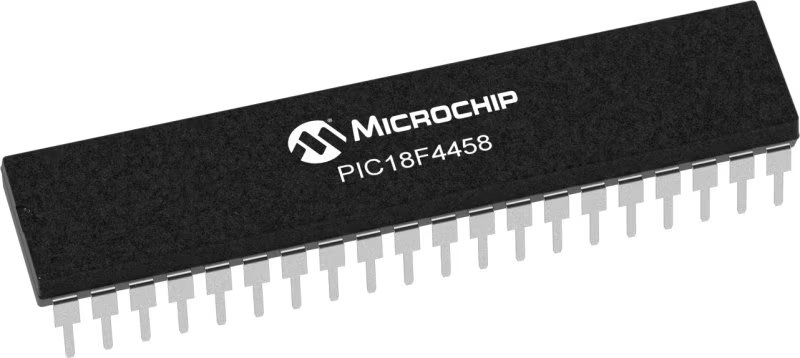
PIC18F4458
Perfectly tailored to meet your low-power RS485 data communication needs, ensuring compatibility and reliability across various applications
A
A
Hardware Overview
How does it work?
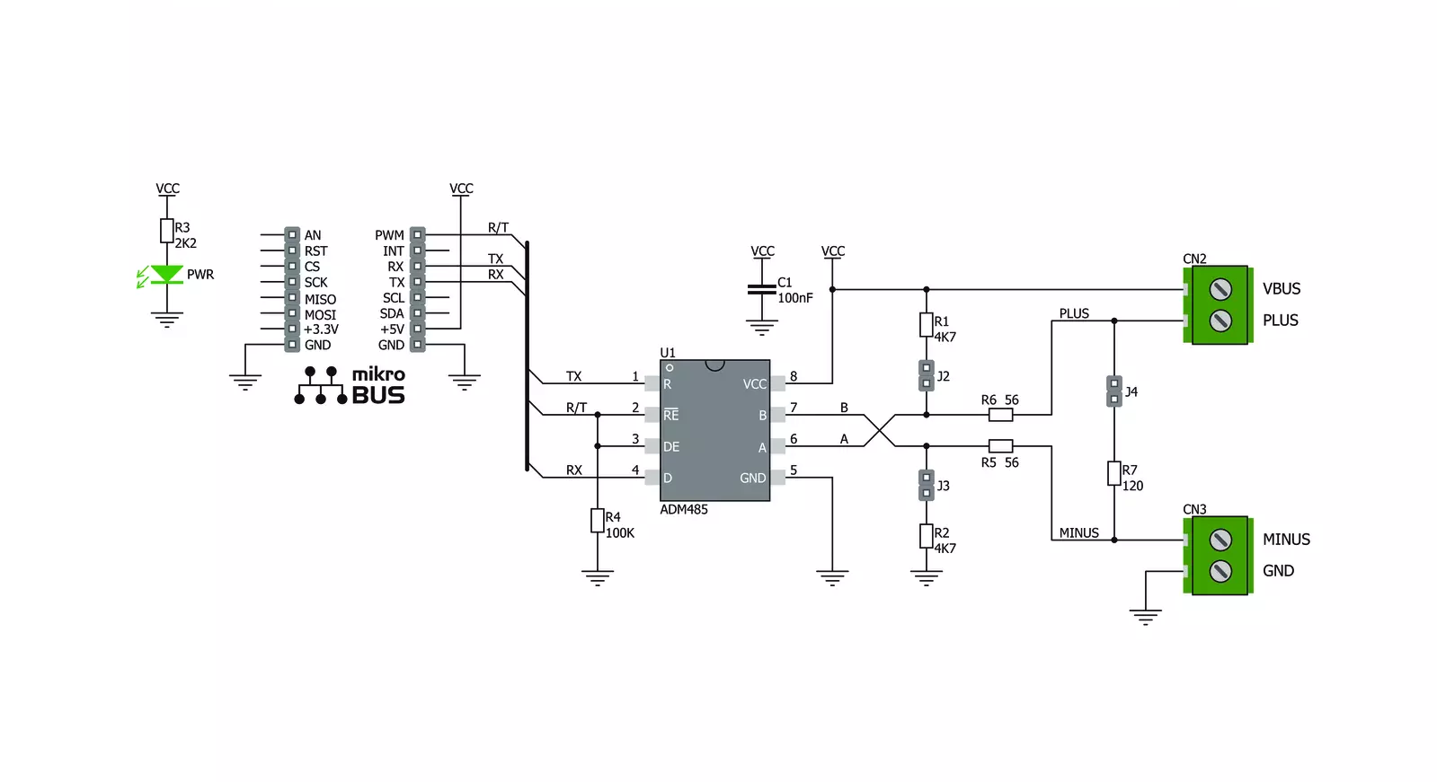
RS485 Click 5V is based on the ADM485, a low-power EIA RS-485 transceiver from Analog Devices. It is a tristate differential line driver and differential input line receiver intended to be used as a physical layer device, often called PHY, providing physical interfacing of the MCU TTL level UART lines with the RS422/485 bus. It is well suited for transmitting smaller data blocks over long distances, using a twisted differential signal pair for both TX and RX signals, allowing for half-duplex asynchronous communication. The ADM485 transceiver consists of separate driver and receiver sections, with Driver Enable and Receiver Enable pins used to enable the appropriate sections. The driver section drives the RS422/485 bus with the signal received on the UART RX line, while the receiver section returns data from the bus to the MCU via the UART TX line. RS422/485 standard only specifies the electrical characteristics of the transmitter and the receiver. It does not specify or recommend any communications protocol, only the physical layer. The top layer communication protocol of choice, such as the MODBUS or similar protocols, can be used. Therefore, RS485 click 5V offers UART RX and TX pins routed to the
appropriate mikroBUS™ TX and RX UART pins. The MCU uses these pins to send data to the RS485 bus in a form determined by the user protocol. The ADM485 IC allows communication with data rates up to 5 Mbps. However, the bus length determines the maximal transfer speed: longer bus lines will result in less transfer speed. The RS422/RS485 bus needs to be terminated with the resistor on both ends (so-called parallel termination), which is equal to the characteristic impedance of the used cable, to prevent line reflections. The RS485 standard prescribes using a twisted pair cable as the data bus. Twisted pair cable tends to cancel common-mode noise and cause cancellation of the magnetic fields generated by the current flowing through each wire, thereby reducing the effective inductance of the pair. The Click board™ is equipped with a jumper that can be used to route the termination resistor of 120Ω between the bus lines. It is also equipped with two more jumpers, labeled as BIAS ENABLE. These jumpers enable bus biasing by using pull-up and pull-down resistors between the bus differential lines and VCC/GND, respectively, preventing certain faulty conditions when nodrivers are
enabled on the bus, in addition to existing IC protection. RS485 Click 5V uses a standard 2-Wire UART interface to communicate with the host MCU with commonly used UART RX and TX lines. Receiver output enable (RE) and driver output enable (DE) pins of the ADM485 are joined together and routed to the R/T pin of the mikroBUS™ socket. When left floating, a pull-down resistor determines the states on these pins, so you have to enable the device by writing a High logic state. Note that DE and RE pins use opposite signal polarities for the active state, making it possible to drive them with a single MCU pin. When a HIGH logic level is applied to the R/T pin, the transmitter becomes activated, while the receiver is deactivated at the same time - and vice versa. The R/T pin acts as a communication direction pin in this configuration. This Click board™ can be operated only with a 5V logic voltage level. The board must perform appropriate logic voltage level conversion before using MCUs with different logic levels. Also, this Click board™ comes equipped with a library containing easy-to-use functions and an example code that can be used as a reference for further development.

Features overview
Development board
Curiosity HPC, standing for Curiosity High Pin Count (HPC) development board, supports 28- and 40-pin 8-bit PIC MCUs specially designed by Microchip for the needs of rapid development of embedded applications. This board has two unique PDIP sockets, surrounded by dual-row expansion headers, allowing connectivity to all pins on the populated PIC MCUs. It also contains a powerful onboard PICkit™ (PKOB), eliminating the need for an external programming/debugging tool, two mikroBUS™ sockets for Click board™ connectivity, a USB connector, a set of indicator LEDs, push button switches and a variable potentiometer. All
these features allow you to combine the strength of Microchip and Mikroe and create custom electronic solutions more efficiently than ever. Each part of the Curiosity HPC development board contains the components necessary for the most efficient operation of the same board. An integrated onboard PICkit™ (PKOB) allows low-voltage programming and in-circuit debugging for all supported devices. When used with the MPLAB® X Integrated Development Environment (IDE, version 3.0 or higher) or MPLAB® Xpress IDE, in-circuit debugging allows users to run, modify, and troubleshoot their custom software and hardware
quickly without the need for additional debugging tools. Besides, it includes a clean and regulated power supply block for the development board via the USB Micro-B connector, alongside all communication methods that mikroBUS™ itself supports. Curiosity HPC development board allows you to create a new application in just a few steps. Natively supported by Microchip software tools, it covers many aspects of prototyping thanks to many number of different Click boards™ (over a thousand boards), the number of which is growing daily.

Microcontroller Overview
MCU Card / MCU
Architecture
PIC
MCU Memory (KB)
24
Silicon Vendor
Microchip
Pin count
40
RAM (Bytes)
2048
Used MCU Pins
mikroBUS™ mapper
Take a closer look
Click board™ Schematic
Step by step
Project assembly

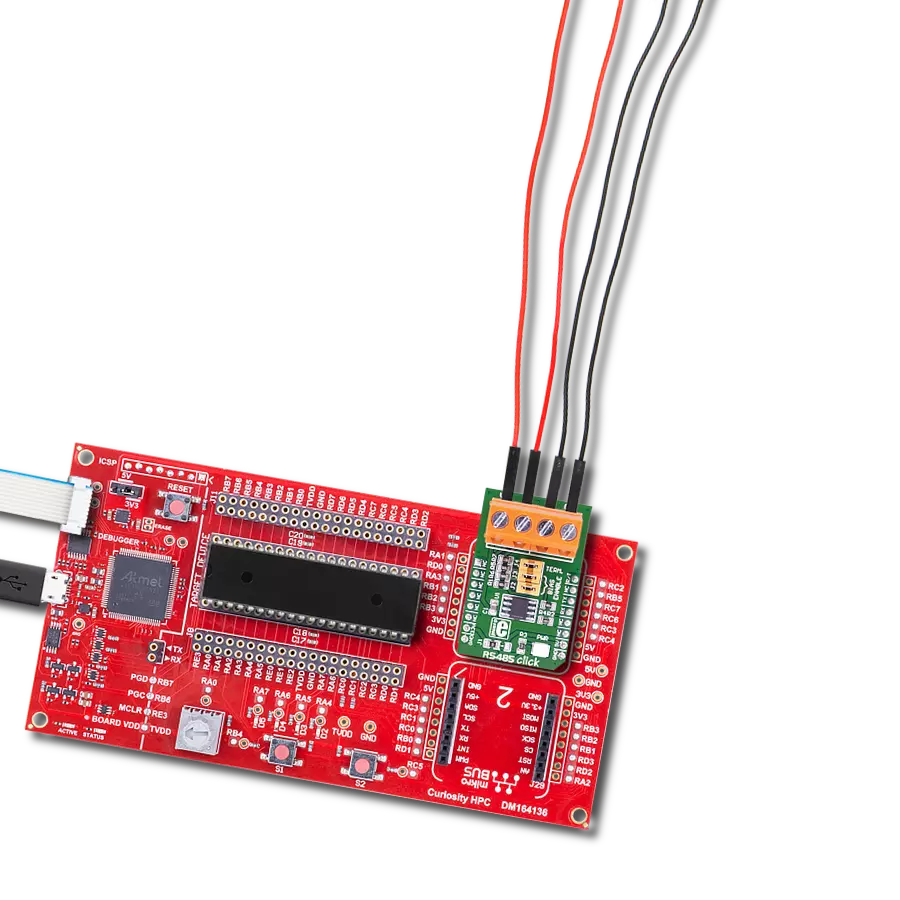
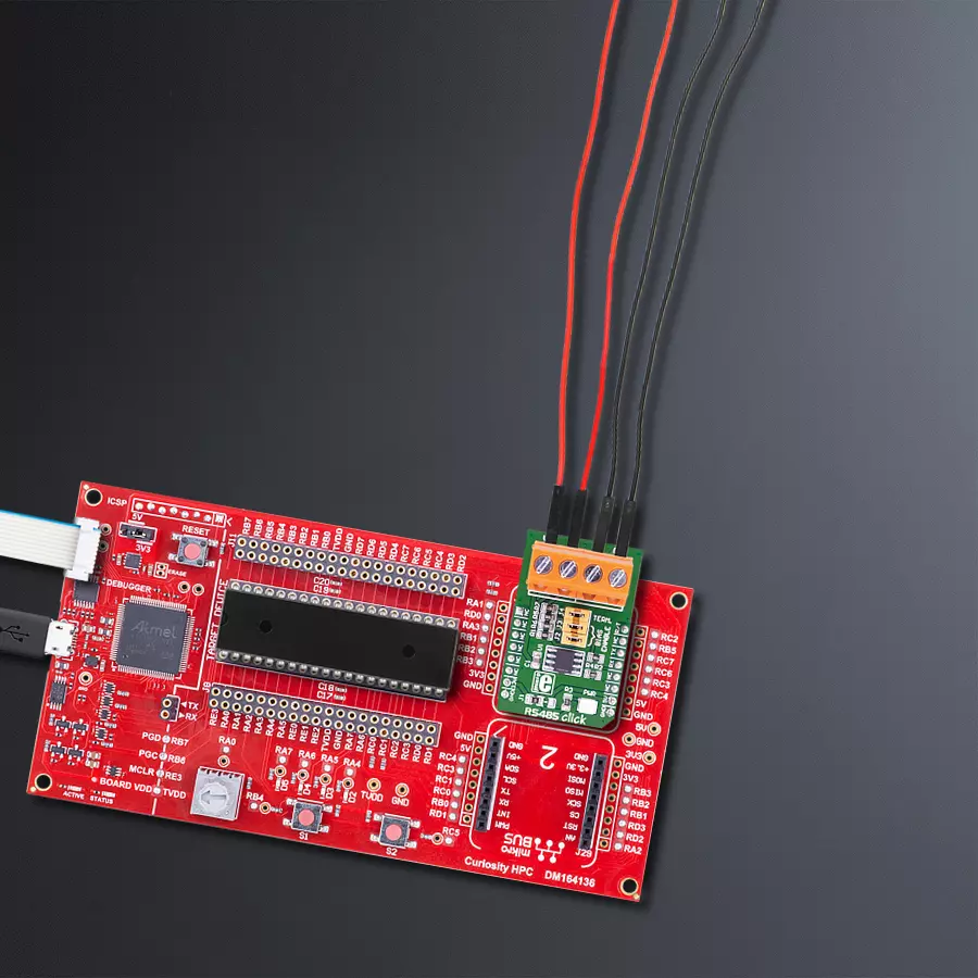
Start by selecting your development board and Click board™. Begin with the Curiosity HPC as your development board.


Software Support
Library Description
This library contains API for RS485 Click 5V driver.
Key functions:
rs4855v_generic_read- This function reads a desired number of data bytes by using UART serial interface.rs4855v_send_command- This function sends a command by using UART serial interface.
Open Source
Code example
The complete application code and a ready-to-use project are available through the NECTO Studio Package Manager for direct installation in the NECTO Studio. The application code can also be found on the MIKROE GitHub account.
/*!
 * @file main.c
 * @brief RS485 5V Click Example.
 *
 * # Description
 * This example reads and processes data from RS485 5V Clicks.
 *
 * The demo application is composed of two sections :
 *
 * ## Application Init
 * Initializes driver and wake-up module.
 *
 * ## Application Task
 * Reads the received data and parses it.
 *
 * ## Additional Function
 * - static void rs4855v_clear_current_rsp_buf ( void ) - The general process of clearing buffer.
 * - static void rs4855v_process ( void ) - The general process of collecting the received data.
 * @author Stefan Ilic
 *
 */
// ------------------------------------------------------------------- INCLUDES

#include "board.h"
#include "log.h"
#include "rs4855v.h"
#include "string.h"

#define PROCESS_COUNTER 10
#define PROCESS_RX_BUFFER_SIZE 100
#define PROCESS_PARSER_BUFFER_SIZE 100

// ------------------------------------------------------------------ VARIABLES

//#define DEMO_APP_RECEIVER
#define DEMO_APP_TRANSMITTER

static rs4855v_t rs4855v;
static log_t logger;

static char current_rsp_buf[ PROCESS_PARSER_BUFFER_SIZE ];
static uint8_t send_data_cnt = 0;

unsigned char demo_message[ 9 ] = { 'M', 'i', 'k', 'r', 'o', 'E', 13, 10, 0 };
// ------------------------------------------------------- ADDITIONAL FUNCTIONS

static void rs4855v_clear_current_rsp_buf ( void ) {
    memset( current_rsp_buf, 0, PROCESS_PARSER_BUFFER_SIZE );
}

static void rs4855v_process ( void ) {
    int16_t rsp_size;
    uint16_t rsp_cnt = 0;

    char uart_rx_buffer[ PROCESS_RX_BUFFER_SIZE ] = { 0 };
    uint8_t check_buf_cnt;
    uint8_t process_cnt = PROCESS_COUNTER;

    // Clear parser buffer
    memset( current_rsp_buf, 0 , PROCESS_PARSER_BUFFER_SIZE );

    while( process_cnt != 0 ) {
        rsp_size = rs4855v_generic_read( &rs4855v, &uart_rx_buffer, PROCESS_RX_BUFFER_SIZE );

        if ( rsp_size > 0 ) {
            // Validation of the received data
            for ( check_buf_cnt = 0; check_buf_cnt < rsp_size; check_buf_cnt++ ) {
                if ( uart_rx_buffer[ check_buf_cnt ] == 0 ) {
                    uart_rx_buffer[ check_buf_cnt ] = 13;
                }
            }
            // Storages data in parser buffer
            rsp_cnt += rsp_size;
            if ( rsp_cnt < PROCESS_PARSER_BUFFER_SIZE ) {
                strncat( current_rsp_buf, uart_rx_buffer, rsp_size );
            }

            // Clear RX buffer
            memset( uart_rx_buffer, 0, PROCESS_RX_BUFFER_SIZE );
        }
        else {
            process_cnt--;

            // Process delay
            Delay_ms ( 100 );
        }
    }
}

// ------------------------------------------------------ APPLICATION FUNCTIONS

void application_init ( void ) {
    log_cfg_t log_cfg;
    rs4855v_cfg_t cfg;

    /**
     * Logger initialization.
     * Default baud rate: 115200
     * Default log level: LOG_LEVEL_DEBUG
     * @note If USB_UART_RX and USB_UART_TX
     * are defined as HAL_PIN_NC, you will
     * need to define them manually for log to work.
     * See @b LOG_MAP_USB_UART macro definition for detailed explanation.
     */
    LOG_MAP_USB_UART( log_cfg );
    log_init( &logger, &log_cfg );

    //  Click initialization.

    rs4855v_cfg_setup( &cfg );
    RS4855V_MAP_MIKROBUS( cfg, MIKROBUS_1 );
    rs4855v_init( &rs4855v, &cfg );
    log_info( &logger, " Application Task " );
    Delay_ms ( 100 );

#ifdef DEMO_APP_TRANSMITTER
    log_printf( &logger, "------------------\r\n" );
    log_printf( &logger, "    Send data:    \r\n" );
    log_printf( &logger, "      MikroE      \r\n" );
    log_printf( &logger, "------------------\r\n" );
    log_printf( &logger, "  Transmit data   \r\n" );
    Delay_ms ( 1000 );

#endif

#ifdef DEMO_APP_RECEIVER
    log_printf( &logger, "------------------\r\n" );

    log_printf( &logger, "   Receive data  \r\n" );
    Delay_ms ( 1000 );
    Delay_ms ( 1000 );
#endif

    log_printf( &logger, "------------------\r\n" );
}

void application_task ( void ) {
#ifdef DEMO_APP_RECEIVER

    rs4855v_process( );
    if ( current_rsp_buf > 0 ) {
        log_printf( &logger, "%s", current_rsp_buf );
        rs4855v_clear_current_rsp_buf( );
    }

#endif

#ifdef DEMO_APP_TRANSMITTER

    rs4855v_send_command( &rs4855v, &demo_message[ 0 ] );
    log_printf( &logger, "\t%s",  &demo_message[ 0 ] );
    Delay_ms ( 1000 );
    Delay_ms ( 1000 );
    log_printf( &logger, "------------------\r\n" );

#endif
}

int main ( void )
{
    /* Do not remove this line or clock might not be set correctly. */
    #ifdef PREINIT_SUPPORTED
    preinit();
    #endif

    application_init( );

    for ( ; ; )
    {
        application_task( );
    }

    return 0;
}

// ------------------------------------------------------------------------ END
Additional Support
Resources
Category:RS485


