Stay connected to your heart's rhythm with BMD101 and PIC18LF46K80
Cardiovascular clarity: ECG excellence for a healthier you
Published Nov 01, 2023
Click board™
ECG 4 Click
Dev. board
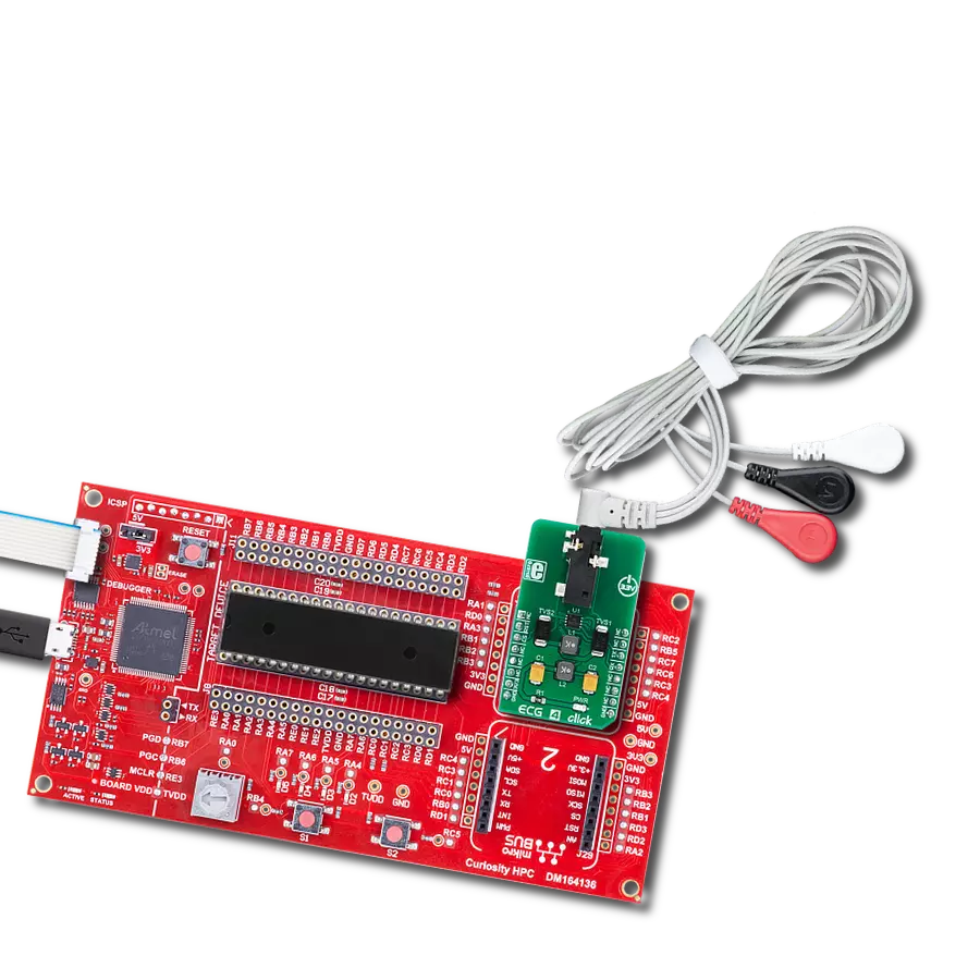
Curiosity HPC
Compiler
NECTO Studio
MCU
PIC18LF46K80
Elevate your heart's performance with our intelligent ECG solution
A
A
Hardware Overview
How does it work?
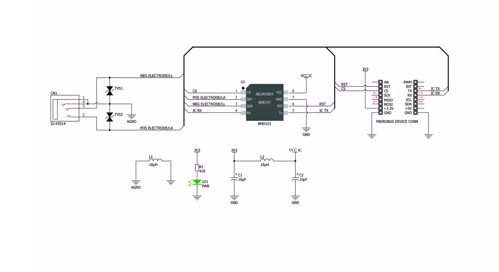
ECG 4 Click is based on the BMD101, a highly integrated specialized bio-signal sensing System-on-Chip (SoC) from NeuroSky, which produces heart-monitoring-related ICs and applications. This IC is the third generation of bio-sensors from this company. It features the complete HR and ECG system on a chip: the analog front-end (AFE) section contains a very precise and low-noise instrumentation amplifier (LNA), which allows very low bio-signals generated by the heart to be amplified enough for the 16-bit ADC to be able to sample them. These voltage impulses are naturally weak and in the range of just a few millivolts, even microvolts. Therefore, any external interferences might obscure them. These interferences might be induced in the human body itself or appear as the result of the activity of other muscles, such as skeletal muscles. Therefore, the input signal from the electrodes is processed by several filtering sections, both in the analog (HP filter at the input) and digital domain (LP filter at 100 Hz and BP filter for removing the 50/60 Hz hum from the mains). However, the correct placement of the
measurement electrodes is crucial for accurate readings. More about the electrodes and their placement can be found in the blog article, as mentioned above. ECG 4 Click allows several types of electrodes to be used. It supports both stainless-steel and silver-chloride electrode types. The electrodes are used to perform differential measurements of the voltage generated by the heart. Therefore, the heart can be monitored from a single plane only - the coronal plane. However, this is quite enough for fitness, heart rate monitoring, and similar applications. The 3.5mm electrodes connector is further protected by two TVS diodes, which prevent electrostatic discharge (ESD) through the SoC and the Click board™. The absence of the electrodes is detectable by the BMD101, which turns the sensor OFF if there is approximately 19 to 25 MΩ between the electrodes. The BMD101 SoC uses the UART interface for communication. The UART interface works at a 57600 baud rate and has 64 bytes of TX FIFO. It uses the 8-1-1 configuration (1 start bit, 8 data bits, 1 stop bit), allowing communication beyond the
host microcontroller. The UART interface could be used with any USB to UART clicks, allowing the PC or smartphone to process and display the HR and ECG data. More information about the UART interface can be found in the datasheet of the BMD101 SoC. However, provided mikroSDK library offers ready-made functions which speed up the software development process. There is a CS pin on the BMD101 SoC, which is routed to the CS pin of the mikroBUS™. This pin should be set to a HIGH logic level to activate the internal power supply. The RESET pin is routed to the mikroBUS™ RST pin. Setting it to a LOW logic level will trigger a RESET of the BMD101. This Click board™ can only be operated with a 3.3V logic voltage level. The board must perform appropriate logic voltage level conversion before using MCUs with different logic levels. However, the Click board™ comes equipped with a library containing functions and an example code that can be used as a reference for further development.


Features overview
Development board
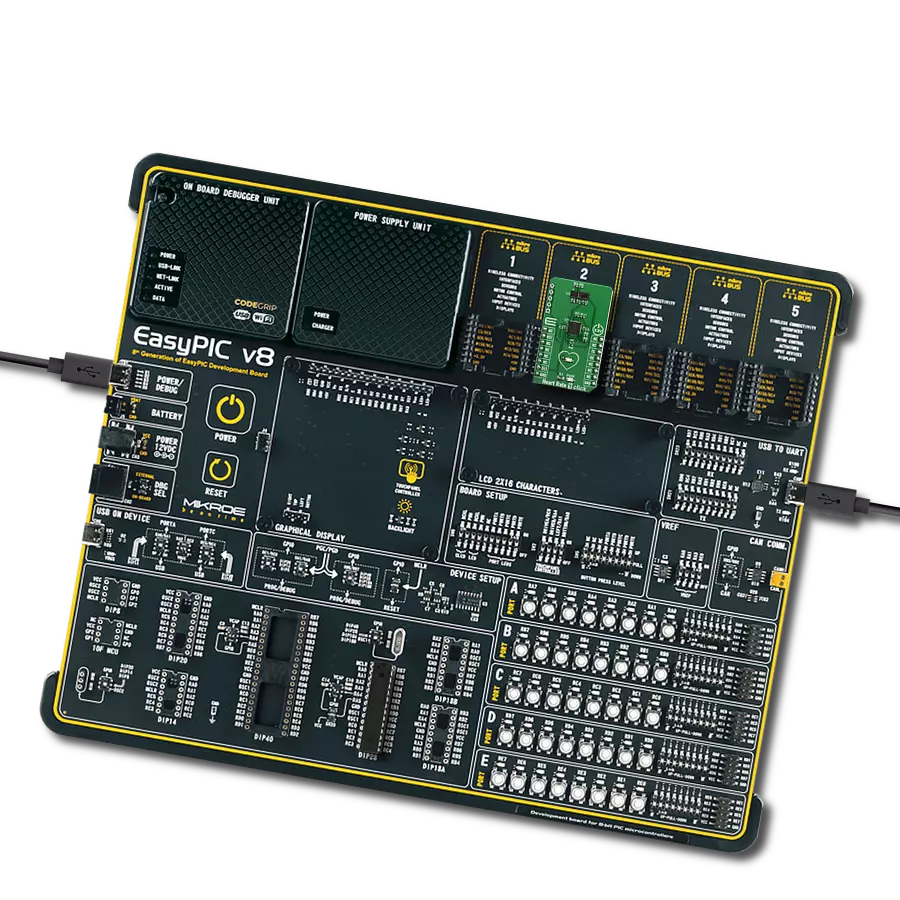
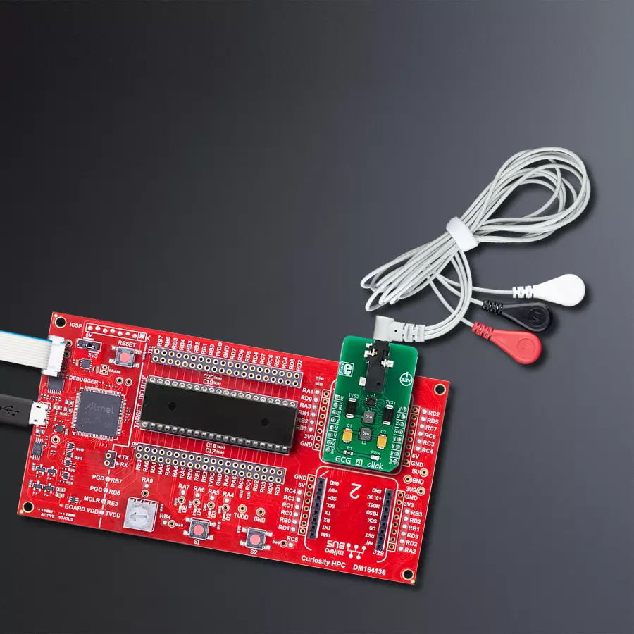
Curiosity HPC, standing for Curiosity High Pin Count (HPC) development board, supports 28- and 40-pin 8-bit PIC MCUs specially designed by Microchip for the needs of rapid development of embedded applications. This board has two unique PDIP sockets, surrounded by dual-row expansion headers, allowing connectivity to all pins on the populated PIC MCUs. It also contains a powerful onboard PICkit™ (PKOB), eliminating the need for an external programming/debugging tool, two mikroBUS™ sockets for Click board™ connectivity, a USB connector, a set of indicator LEDs, push button switches and a variable potentiometer. All
these features allow you to combine the strength of Microchip and Mikroe and create custom electronic solutions more efficiently than ever. Each part of the Curiosity HPC development board contains the components necessary for the most efficient operation of the same board. An integrated onboard PICkit™ (PKOB) allows low-voltage programming and in-circuit debugging for all supported devices. When used with the MPLAB® X Integrated Development Environment (IDE, version 3.0 or higher) or MPLAB® Xpress IDE, in-circuit debugging allows users to run, modify, and troubleshoot their custom software and hardware
quickly without the need for additional debugging tools. Besides, it includes a clean and regulated power supply block for the development board via the USB Micro-B connector, alongside all communication methods that mikroBUS™ itself supports. Curiosity HPC development board allows you to create a new application in just a few steps. Natively supported by Microchip software tools, it covers many aspects of prototyping thanks to many number of different Click boards™ (over a thousand boards), the number of which is growing daily.

Microcontroller Overview
MCU Card / MCU
Architecture
PIC
MCU Memory (KB)
64
Silicon Vendor
Microchip
Pin count
40
RAM (Bytes)
3648
You complete me!
Accessories
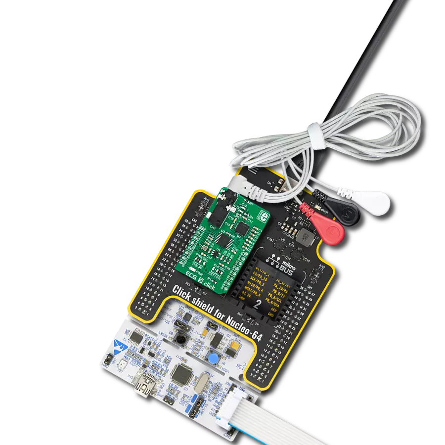
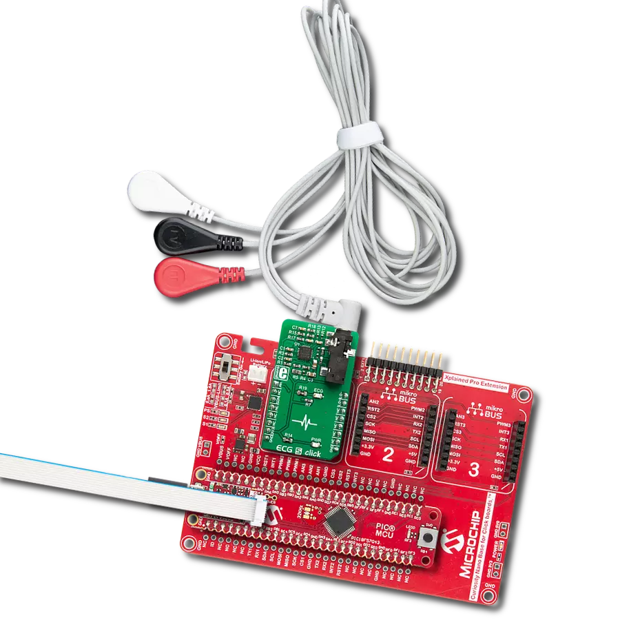
3-wire ECG/EMG cable comes with a convenient 3.5mm phone jack, and it is designed for electrocardiogram recording. This 1m cable is a practical companion for medical professionals and enthusiasts. To complement this cable, you can also use single-use adhesive ECG/EMG electrodes measuring 48x34mm, each equipped with an ECG/EMG cable stud adapter. These electrodes ensure a seamless experience when paired with our ECG/EMG cable and guarantee reliable ECG/EMG signal transmission for comprehensive cardiac monitoring. Trust in the accuracy and convenience of this setup to effortlessly record electrocardiograms and electromyograms with confidence.

Used MCU Pins
mikroBUS™ mapper
Take a closer look
Click board™ Schematic
Step by step
Project assembly

Start by selecting your development board and Click board™. Begin with the Curiosity HPC as your development board.


Track your results in real time
Application Output
1. Application Output - In Debug mode, the 'Application Output' window enables real-time data monitoring, offering direct insight into execution results. Ensure proper data display by configuring the environment correctly using the provided tutorial.

2. UART Terminal - Use the UART Terminal to monitor data transmission via a USB to UART converter, allowing direct communication between the Click board™ and your development system. Configure the baud rate and other serial settings according to your project's requirements to ensure proper functionality. For step-by-step setup instructions, refer to the provided tutorial.

3. Plot Output - The Plot feature offers a powerful way to visualize real-time sensor data, enabling trend analysis, debugging, and comparison of multiple data points. To set it up correctly, follow the provided tutorial, which includes a step-by-step example of using the Plot feature to display Click board™ readings. To use the Plot feature in your code, use the function: plot(*insert_graph_name*, variable_name);. This is a general format, and it is up to the user to replace 'insert_graph_name' with the actual graph name and 'variable_name' with the parameter to be displayed.

Software Support
Library Description
This library contains API for ECG 4 Click driver.
Key functions:
ecg4_uart_isr- Function performs the uart interrupt routine, reads a data from uart rx buffer and makes a response from the BMD101 deviceecg4_enable_ldo_ctrl- Function powers up or down control of LDO (Low Drop Out)ecg4_generic_read- Generic read function
Open Source
Code example
The complete application code and a ready-to-use project are available through the NECTO Studio Package Manager for direct installation in the NECTO Studio. The application code can also be found on the MIKROE GitHub account.
/*!
 * \file
 * \brief Ecg4 Click example
 *
 * # Description
 * This example reads and processes data from ECG 4 Clicks.
 *
 * The demo application is composed of two sections :
 *
 * ## Application Init
 * Initializes the driver, sets the driver handler and enables the Click board.
 *
 * ## Application Task
 * Reads the received data and parses it on the USB UART if the response buffer is ready.
 *
 * ## Additional Function
 * - ecg4_process - The general process of collecting data the module sends.
 * - plot_data - Displays raw ECG data.
 * - log_data - Displays the real time BPM heart rate.
 * - process_response - Checks the response and displays raw ECG data or heart rate (BPM).
 * - make_response - Driver handler function which stores data in the response buffer.
 *
 * @note
 * Use the Serial Plot application for data plotting.
 *
 * \author MikroE Team
 *
 */
// ------------------------------------------------------------------- INCLUDES

#include "board.h"
#include "log.h"
#include "ecg4.h"
#include "string.h"

// ------------------------------------------------------------------ VARIABLES

static ecg4_t ecg4;
static log_t logger;

static uint8_t response[ 256 ];
static uint8_t row_counter;
static uint8_t row_size_cnt;

// ------------------------------------------------------- ADDITIONAL FUNCTIONS

static void ecg4_process ( void )
{
    int32_t rx_size;
    char rx_buff;

    rx_size = ecg4_generic_read( &ecg4, &rx_buff, 1 );

    if ( rx_size > 0 )
    {
        ecg4_uart_isr( &ecg4, rx_buff );
    }
}

void plot_data ( int16_t plot_data )
{
    log_printf( &logger, "%d;\r\n", plot_data );
}

void log_data ( uint8_t code_val, uint8_t data_val )
{
    if ( code_val == ECG4_HEART_RATE_CODE_BYTE )
    {
        log_printf( &logger, "** Real-time Heart Rate : %d BPM **\r\n", ( int16_t ) data_val );
    }
}

void make_response ( uint8_t *op_code, uint8_t *row_size, uint8_t *rx_buff, uint8_t *row_cnt )
{
    uint8_t idx_cnt;

    if ( *row_cnt == 0 )
    {
        row_size_cnt = 0;
    }

    response[ row_size_cnt ] = *op_code;
    response[ row_size_cnt + 1 ] = *row_size;

    for ( idx_cnt = 0; idx_cnt < *row_size; idx_cnt++ )
    {
        response[ row_size_cnt + 2 + idx_cnt ] = rx_buff[ idx_cnt ];
    }

    row_size_cnt += ( *row_size + 2 );
    row_counter = *row_cnt;
}

void process_response( )
{
    uint8_t cnt;
    uint8_t idx_cnt;
    int16_t raw_data;

    idx_cnt = 0;

    for ( cnt = 0; cnt <= row_counter; cnt++ )
    {
        if ( response[ idx_cnt ] == ECG4_RAW_DATA_CODE_BYTE )
        {
            raw_data = response[ idx_cnt + 2 ];
            raw_data <<= 8;
            raw_data |= response[ idx_cnt + 3 ];

            plot_data( raw_data );
        }

        if ( response[ idx_cnt ] == ECG4_HEART_RATE_CODE_BYTE )
        {
            log_data( response[ idx_cnt ], response[ idx_cnt + 2 ] );
        }

        idx_cnt += ( response[ idx_cnt + 1 ] + 2 );
    }
}

// ------------------------------------------------------ APPLICATION FUNCTIONS

void application_init ( void )
{
    log_cfg_t log_cfg;
    ecg4_cfg_t cfg;

    /**
     * Logger initialization.
     * Default baud rate: 115200
     * Default log level: LOG_LEVEL_DEBUG
     * @note If USB_UART_RX and USB_UART_TX
     * are defined as HAL_PIN_NC, you will
     * need to define them manually for log to work.
     * See @b LOG_MAP_USB_UART macro definition for detailed explanation.
     */
    LOG_MAP_USB_UART( log_cfg );
    log_init( &logger, &log_cfg );
    log_info( &logger, "---- Application Init ----" );

    //  Click initialization.

    ecg4_cfg_setup( &cfg );
    ECG4_MAP_MIKROBUS( cfg, MIKROBUS_1 );
    ecg4_init( &ecg4, &cfg );

    ecg4.driver_hdl = make_response;
    Delay_ms ( 500 );

    ecg4_module_reset ( &ecg4 );
    ecg4_enable_ldo_ctrl ( &ecg4, ECG4_ENABLE_LDO_CTRL );

    Delay_ms ( 1000 );
}

void application_task ( void )
{
    ecg4_process(  );
    if ( ecg4_responseReady( &ecg4 ) )
    {
        process_response( );
    }
}

int main ( void )
{
    /* Do not remove this line or clock might not be set correctly. */
    #ifdef PREINIT_SUPPORTED
    preinit();
    #endif

    application_init( );

    for ( ; ; )
    {
        application_task( );
    }

    return 0;
}


// ------------------------------------------------------------------------ END
Additional Support
Resources
Category:Biometrics