Immediately seize and safeguard essential data in the event of a power disruption with CY15B116QSN and PIC18F4682
Unlock the future of memory
Published Nov 01, 2023
Click board™
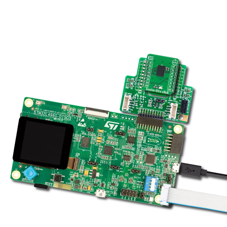
Excelon-Ultra Click
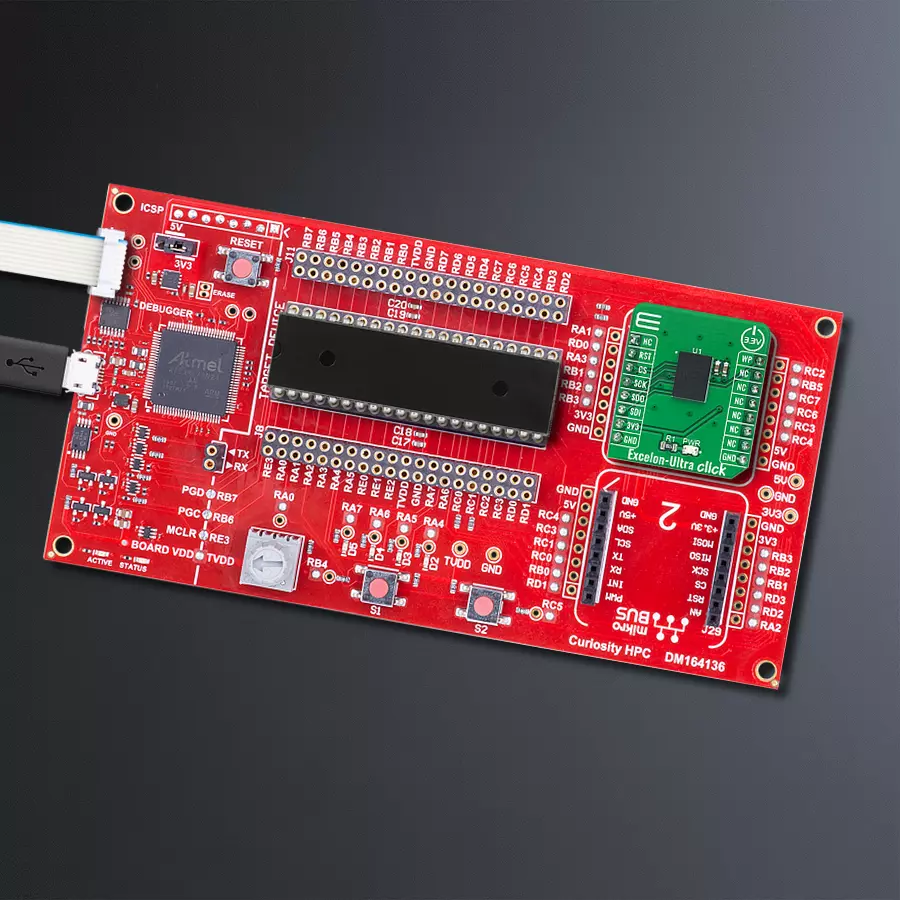
Dev. board
Curiosity HPC
Compiler
NECTO Studio
MCU
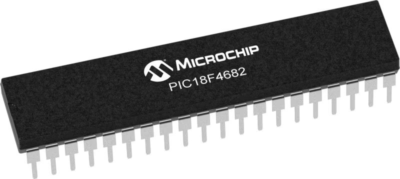
PIC18F4682
Boost the efficiency and speed of your design with FRAM memory technology
A
A
Hardware Overview
How does it work?
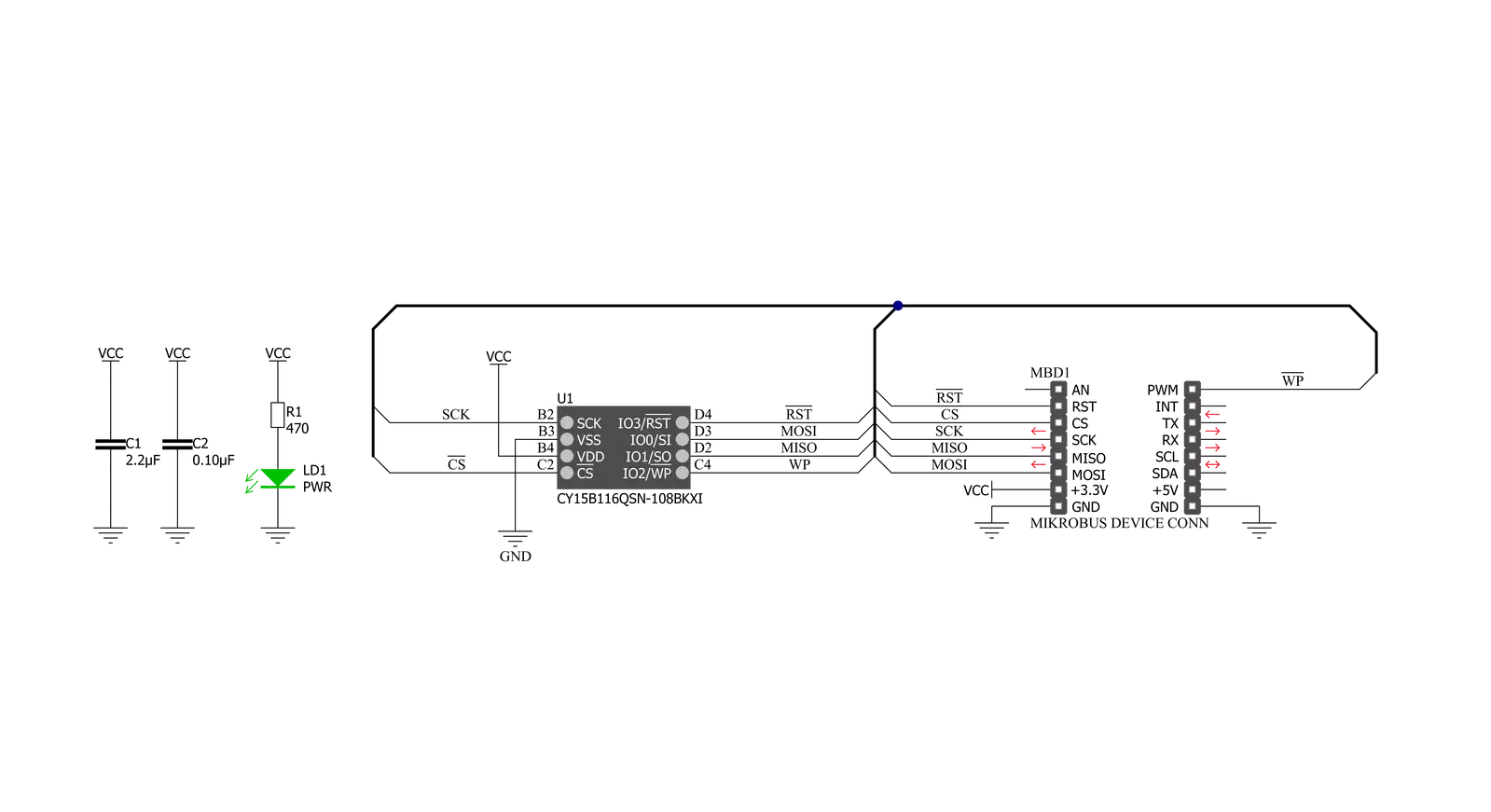
Excelon-Ultra Click is based on the CY15B116QSN, a high-performance 16-Mbit nonvolatile memory employing an advanced Infineon ferroelectric process. The memory array is logically organized as 2,097,152 × 8 bits and is accessed using an industry-standard serial peripheral interface (SPI) bus. The CY15B116QSN combines a 16-Mbit F-RAM with the high-speed Quad SPI SDR and DDR interfaces, enhancing FRAM technology's nonvolatile write capability. The key differences between the CY15B116QSN and a serial flash are the FRAM's superior write performance, high endurance, and lower power consumption. The CY15B116QSN is ideal for nonvolatile memory applications requiring frequent or rapid writes. Examples range from data collection, where the number of write cycles may be critical, to demanding industrial controls, where the long
write time of serial Flash can cause data loss. Excelon-Ultra Click communicates with MCU using an industry-standard SPI interface supporting the two most common modes, SPI Mode 0 and 3, with a maximum frequency 108MHz. Data is written to the memory array immediately after each byte is successfully transferred to the device. The following bus cycle can commence without the need for data polling. It supports 1e14 read/write cycles, or 100 million times more write cycles than EEPROM. In addition, the CY15B116QSN offers substantial write endurance compared to other nonvolatile memories. Furthermore, this Click board™ provides additional hardware-controlled functions. The configurable Write Protection function routed on the PWM pin of the mikroBUS™ socket protects all registers (including status and
configuration) from write operations when the SRWD bit (SR1[7]) is set to '1'. The WP pin must be held high to inhibit all the write operations to registers. When this pin is high, all memory and register writes are prohibited, and the address counter is not incremented. Also, it has a Reset feature routed to the RST pin on the mikroBUS™ socket, which, with a low logic level, puts the CY15B116QSN into a Reset state and, with a high level, operates the module normally. This Click board™ can be operated only with a 3.3V logic voltage level. The board must perform appropriate logic voltage level conversion before using MCUs with different logic levels. Also, it comes equipped with a library containing functions and an example code that can be used as a reference for further development.


Features overview
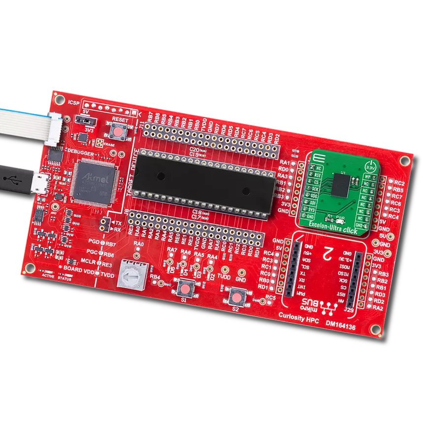
Development board
Curiosity HPC, standing for Curiosity High Pin Count (HPC) development board, supports 28- and 40-pin 8-bit PIC MCUs specially designed by Microchip for the needs of rapid development of embedded applications. This board has two unique PDIP sockets, surrounded by dual-row expansion headers, allowing connectivity to all pins on the populated PIC MCUs. It also contains a powerful onboard PICkit™ (PKOB), eliminating the need for an external programming/debugging tool, two mikroBUS™ sockets for Click board™ connectivity, a USB connector, a set of indicator LEDs, push button switches and a variable potentiometer. All
these features allow you to combine the strength of Microchip and Mikroe and create custom electronic solutions more efficiently than ever. Each part of the Curiosity HPC development board contains the components necessary for the most efficient operation of the same board. An integrated onboard PICkit™ (PKOB) allows low-voltage programming and in-circuit debugging for all supported devices. When used with the MPLAB® X Integrated Development Environment (IDE, version 3.0 or higher) or MPLAB® Xpress IDE, in-circuit debugging allows users to run, modify, and troubleshoot their custom software and hardware
quickly without the need for additional debugging tools. Besides, it includes a clean and regulated power supply block for the development board via the USB Micro-B connector, alongside all communication methods that mikroBUS™ itself supports. Curiosity HPC development board allows you to create a new application in just a few steps. Natively supported by Microchip software tools, it covers many aspects of prototyping thanks to many number of different Click boards™ (over a thousand boards), the number of which is growing daily.

Microcontroller Overview
MCU Card / MCU
Architecture
PIC
MCU Memory (KB)
80
Silicon Vendor
Microchip
Pin count
40
RAM (Bytes)
3328
Used MCU Pins
mikroBUS™ mapper
Take a closer look
Click board™ Schematic
Step by step
Project assembly

Start by selecting your development board and Click board™. Begin with the Curiosity HPC as your development board.


Track your results in real time
Application Output
1. Application Output - In Debug mode, the 'Application Output' window enables real-time data monitoring, offering direct insight into execution results. Ensure proper data display by configuring the environment correctly using the provided tutorial.

2. UART Terminal - Use the UART Terminal to monitor data transmission via a USB to UART converter, allowing direct communication between the Click board™ and your development system. Configure the baud rate and other serial settings according to your project's requirements to ensure proper functionality. For step-by-step setup instructions, refer to the provided tutorial.

3. Plot Output - The Plot feature offers a powerful way to visualize real-time sensor data, enabling trend analysis, debugging, and comparison of multiple data points. To set it up correctly, follow the provided tutorial, which includes a step-by-step example of using the Plot feature to display Click board™ readings. To use the Plot feature in your code, use the function: plot(*insert_graph_name*, variable_name);. This is a general format, and it is up to the user to replace 'insert_graph_name' with the actual graph name and 'variable_name' with the parameter to be displayed.

Software Support
Library Description
This library contains API for Excelon-Ultra Click driver.
Key functions:
excelonultra_write_data_to_memory- Write data starting from specified memory addressexcelonultra_read_data_from_memory- Read data starting from specified memory addressexcelonultra_clear_data_from_memory-Clears data starting from specified memory address
Open Source
Code example
The complete application code and a ready-to-use project are available through the NECTO Studio Package Manager for direct installation in the NECTO Studio. The application code can also be found on the MIKROE GitHub account.
/*!
 * @file main.c
 * @brief ExcelonUltra Click example
 *
 * # Description
 * This example is showcase of device and it's library abillity.
 * In this example is shown device ID, ability to manipulate with memory.
 * After default configuration device IDs are logged. After that application
 * Writes data to memory, reads data from memory, clears data from memory and
 * checks if data is cleard by reading that same memory address.
 *
 * The demo application is composed of two sections :
 *
 * ## Application Init
 * Initializes MCU modules for communication used in this application (UART, SPI).
 * Calls default configuration that resets device, reads IDs, and enables writing to
 * memory and sets all RAM memory to be free for conrol.
 *
 * ## Application Task
 * Write data to memory, read data from memory. After that clears that memory address,
 * and checks if it's cleared by reading data. On every iteration of the fucntion
 * writing data is changed between "MikroE" and "Excelon-Ultra Click"
 *
 * @author Luka Filipovic
 *
 */

#include "board.h"
#include "log.h"
#include "excelonultra.h"

#define MIKROE_DATA "MikroE"
#define CLICK_DATA "Excelon-Ultra Click"

static excelonultra_t excelonultra;
static log_t logger;

void application_init ( void )
{
    log_cfg_t log_cfg;  /**< Logger config object. */
    excelonultra_cfg_t excelonultra_cfg;  /**< Click config object. */

    /**
     * Logger initialization.
     * Default baud rate: 115200
     * Default log level: LOG_LEVEL_DEBUG
     * @note If USB_UART_RX and USB_UART_TX
     * are defined as HAL_PIN_NC, you will
     * need to define them manually for log to work.
     * See @b LOG_MAP_USB_UART macro definition for detailed explanation.
     */
    LOG_MAP_USB_UART( log_cfg );
    log_init( &logger, &log_cfg );
    log_info( &logger, " Application Init " );

    // Click initialization.
    excelonultra_cfg_setup( &excelonultra_cfg );
    EXCELONULTRA_MAP_MIKROBUS( excelonultra_cfg, MIKROBUS_1 );
    err_t init_flag  = excelonultra_init( &excelonultra, &excelonultra_cfg );
    if ( init_flag == SPI_MASTER_ERROR )
    {
        log_error( &logger, " Application Init Error. " );
        log_info( &logger, " Please, run program again... " );

        for ( ; ; );
    }

    excelonultra_default_cfg ( &excelonultra );

    log_printf( &logger, " > Manufacturer ID: 0x%.4X\r\n", excelonultra.manufacturer_id );
    log_printf( &logger, " > Product ID: 0x%.4X\r\n", excelonultra.product_id );
    log_printf( &logger, " > Density ID: 0x%.2X\r\n", excelonultra.density_id );
    log_printf( &logger, " > Die Rev: 0x%.2X\r\n", excelonultra.die_rev );

    log_printf( &logger, " > Unique ID: 0x%.2X" , excelonultra.unique_id[ 7 ] );
    log_printf( &logger, "%.2X" , excelonultra.unique_id[ 6 ] );
    log_printf( &logger, "%.2X" , excelonultra.unique_id[ 5 ] );
    log_printf( &logger, "%.2X" , excelonultra.unique_id[ 4 ] );
    log_printf( &logger, "%.2X" , excelonultra.unique_id[ 3 ] );
    log_printf( &logger, "%.2X" , excelonultra.unique_id[ 2 ] );
    log_printf( &logger, "%.2X" , excelonultra.unique_id[ 1 ] );
    log_printf( &logger, "%.2X\r\n" , excelonultra.unique_id[ 0 ] );

    Delay_ms ( 1000 );
    log_info( &logger, " Application Task " );
}

void application_task ( void )
{
    static uint32_t memory_address = 0x00000055;
    static uint8_t data_selection = 1;
    static uint8_t write_len;
    char to_write[ 50 ] = { 0 };
    char read_from[ 50 ] = { 0 };

    if (data_selection)
    {
        strcpy( to_write, MIKROE_DATA );
        data_selection = !data_selection;
    }
    else
    {
        strcpy( to_write, CLICK_DATA );
        data_selection = !data_selection;
    }
    write_len = strlen( to_write );

    log_printf( &logger, " > Writing data to memory: %s\r\n", to_write );
    excelonultra_write_data_to_memory( &excelonultra, memory_address, to_write, write_len );

    Delay_ms ( 500 );

    excelonultra_read_data_from_memory( &excelonultra, memory_address, read_from, write_len );
    log_printf( &logger, " > Read data from memory: %s\r\n", read_from );

    Delay_ms ( 500 );

    log_printf( &logger, " > Clearing data from memory\r\n" );
    excelonultra_clear_data_from_memory( &excelonultra, memory_address, write_len );

    Delay_ms ( 500 );

    excelonultra_read_data_from_memory( &excelonultra, memory_address, read_from, write_len );
    log_printf( &logger, " > Read data from memory: %s\r\n", read_from );

    log_printf( &logger, "***********************************\r\n" );
    Delay_ms ( 500 );
}

int main ( void )
{
    /* Do not remove this line or clock might not be set correctly. */
    #ifdef PREINIT_SUPPORTED
    preinit();
    #endif

    application_init( );

    for ( ; ; )
    {
        application_task( );
    }

    return 0;
}

// ------------------------------------------------------------------------ END
Additional Support
Resources
Category:FRAM