Ensure dependable data transmission in industrial environments with Metis-II (2607021183000) and PIC32MZ2048EFH100
Low-power 868MHz radio solution compliant with wireless M-BUS EN13757-4:2013 and Open Metering System (OMS) standards

Published Oct 07, 2024
Click board™
M-BUS RF 3 Click
Dev. board
Flip&Click PIC32MZ
Compiler
NECTO Studio
MCU
PIC32MZ2048EFH100
Excel in smart metering, home automation, and industrial control applications
A
A
Hardware Overview
How does it work?
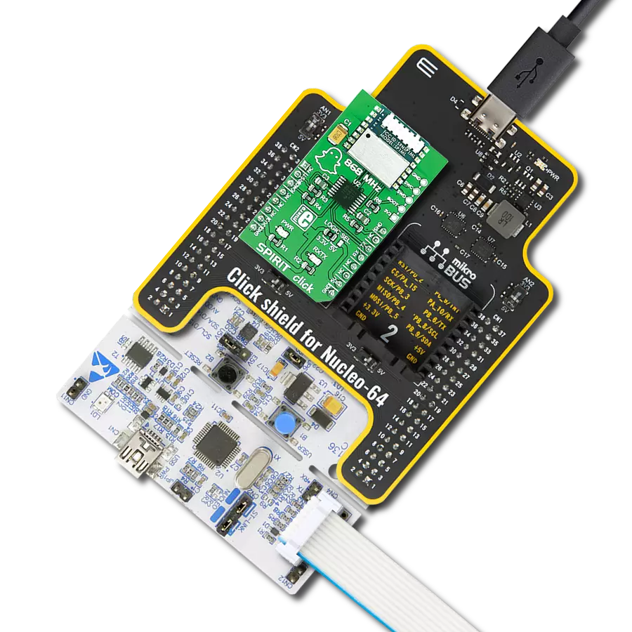
M-BUS RF 3 Click is based on the Metis-II (2607021183000), a high-power radio module from Würth Elektronik, operating at 868MHz. This module integrates an MSP430 microcontroller and a CC1125 RF chip-set, offering an efficient and cost-effective communication solution. The Metis-II module adheres to the Wireless M-BUS EN13757-4:2013 standard and supports the Open Metering System (OMS), ensuring wide compatibility in utility metering applications. An increased RF output power of +14dBm and sensitivity up to -106dBm enables reliable wireless communication over distances up to 1000 meters in line-of-sight conditions. Designed with energy efficiency in mind, the module includes low-power functions such as Wake-On-Radio and adjustable RF data rates, making it ideal for long-range, low-power
wireless applications. Additionally, it features AES-128 encryption for secure data transmission, ensuring robust communication for metering systems. Communication between the Metis-II and the host MCU is made through a UART interface, using the standard UART RX and TX pins and hardware flow control pins (CTS/RTS). The module communicates at 115200bps by default, allowing efficient data exchange. The board includes a reset pin (RST) and a RESET button for resetting the module, and two LED indicators for user interaction: an orange TX LED signaling transmission activity and a yellow RX LED indicating reception. In addition to the UART interface, this Click board™ also features a USB Type-C connector, enabling power supply and configuration through a PC. This is made possible
by the CP2102N, a highly integrated USB-to-UART bridge, and the NCP1117 LDO regulator, which converts the USB supply to the required 3.3V for the module allowing for standalone operation. The board is designed to interface with 868MHz antennas, such as the Rubber 868MHz Antenna offered by MIKROE. It includes a u.Fl connector, necessitating an IPEX-SMA cable adapter, also available from MIKROE, to ensure proper antenna connection. This Click board™ can be operated only with a 3.3V logic voltage level. The board must perform appropriate logic voltage level conversion before using MCUs with different logic levels. Also, it comes equipped with a library containing functions and an example code that can be used as a reference for further development.

Features overview
Development board
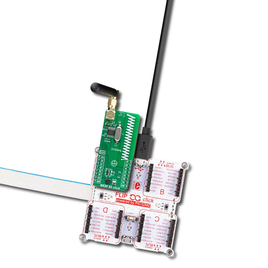
Flip&Click PIC32MZ is a compact development board designed as a complete solution that brings the flexibility of add-on Click boards™ to your favorite microcontroller, making it a perfect starter kit for implementing your ideas. It comes with an onboard 32-bit PIC32MZ microcontroller, the PIC32MZ2048EFH100 from Microchip, four mikroBUS™ sockets for Click board™ connectivity, two USB connectors, LED indicators, buttons, debugger/programmer connectors, and two headers compatible with Arduino-UNO pinout. Thanks to innovative manufacturing technology,
it allows you to build gadgets with unique functionalities and features quickly. Each part of the Flip&Click PIC32MZ development kit contains the components necessary for the most efficient operation of the same board. In addition, there is the possibility of choosing the Flip&Click PIC32MZ programming method, using the chipKIT bootloader (Arduino-style development environment) or our USB HID bootloader using mikroC, mikroBasic, and mikroPascal for PIC32. This kit includes a clean and regulated power supply block through the USB Type-C (USB-C) connector. All communication
methods that mikroBUS™ itself supports are on this board, including the well-established mikroBUS™ socket, user-configurable buttons, and LED indicators. Flip&Click PIC32MZ development kit allows you to create a new application in minutes. Natively supported by Mikroe software tools, it covers many aspects of prototyping thanks to a considerable number of different Click boards™ (over a thousand boards), the number of which is growing every day.

Microcontroller Overview
MCU Card / MCU

Architecture
PIC32
MCU Memory (KB)
2048
Silicon Vendor
Microchip
Pin count
100
RAM (Bytes)
524288
You complete me!
Accessories
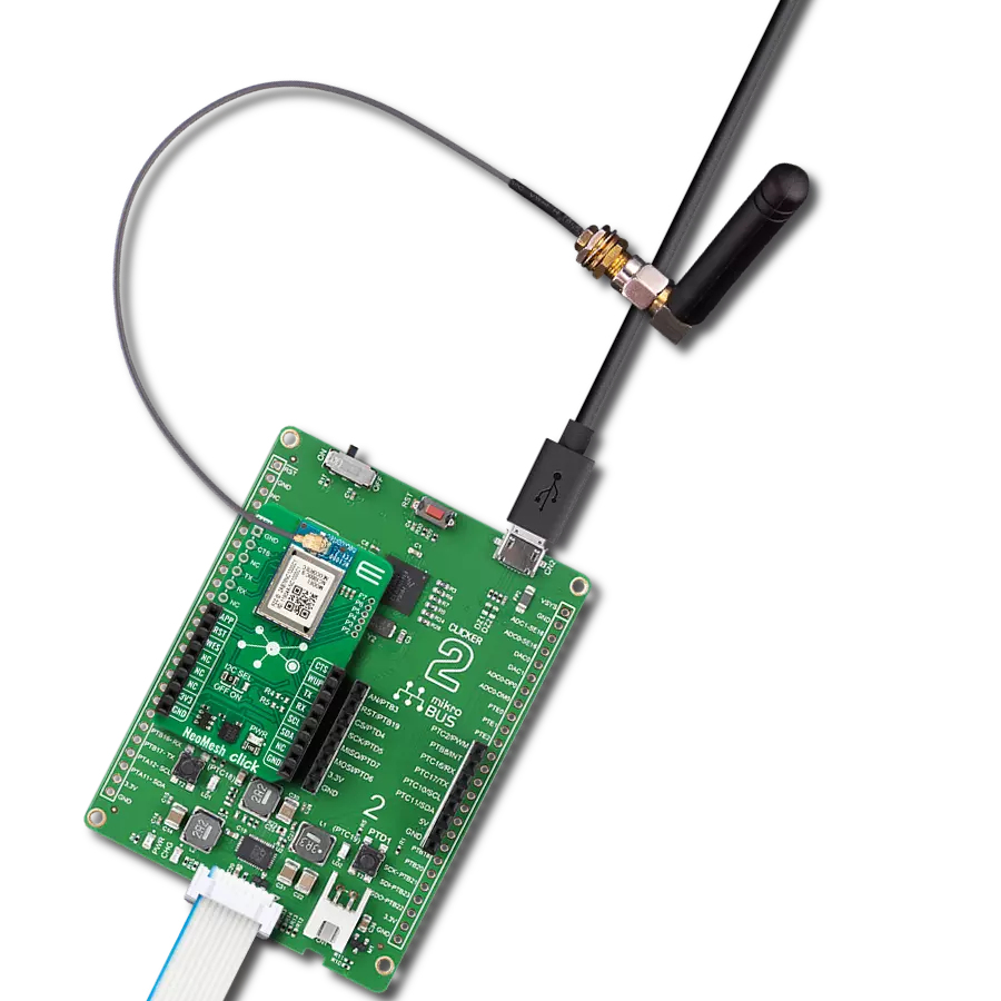
868MHz right-angle rubber antenna is a compact and versatile solution for wireless communication. Operating within the frequency range of 868-915MHz, it ensures optimal signal reception and transmission. With a 50-ohm impedance, it's compatible with various devices and systems. This antenna boasts a 2dB gain, enhancing signal strength and extending communication range. Its vertical polarization further contributes to signal clarity. Designed to handle up to 50W of input power, it's a robust choice for various applications. Measuring just 48mm in length, this antenna is both discreet and practical. Its SMA male connector ensures a secure and reliable connection to your equipment. Whether you're working with IoT devices, remote sensors, or other wireless technologies, the 868MHz right-angle antenna offers the performance and flexibility you need for seamless communication.

IPEX-SMA cable is a type of RF (radio frequency) cable assembly. "IPEX" refers to the IPEX connector, a miniature coaxial connector commonly used in small electronic devices. "SMA" stands for SubMiniature Version A and is another coaxial connector commonly used in RF applications. An IPEX-SMA cable assembly has an IPEX connector on one end and an SMA connector on the other, allowing it to connect devices or components that use these specific connectors. These cables are often used in applications like WiFi or cellular antennas, GPS modules, and other RF communication systems where a reliable and low-loss connection is required.

Used MCU Pins
mikroBUS™ mapper
Take a closer look
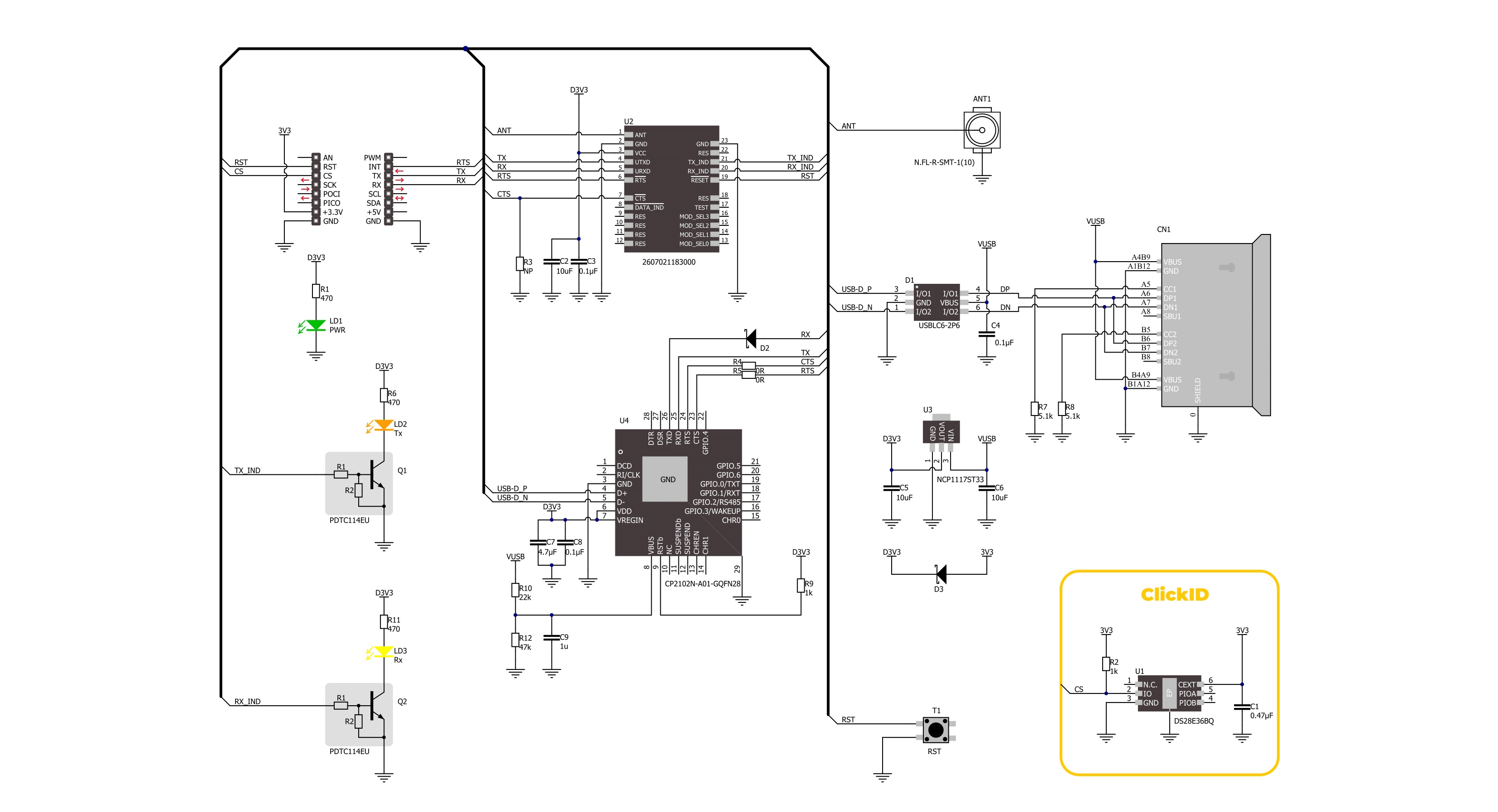
Click board™ Schematic
Step by step
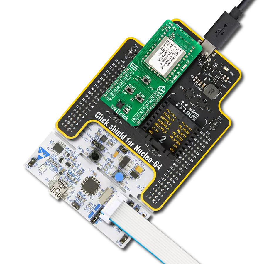
Project assembly

Start by selecting your development board and Click board™. Begin with the Flip&Click PIC32MZ as your development board.


Software Support
Library Description
This library contains API for M-BUS RF 3 Click driver.
Key functions:
mbusrf3_set_rst_pin- This function is used to set reset pin state.mbusrf3_send_command- This function is used to send a desired command.mbusrf3_send_data- This function is used to data in transmitter mode.
Open Source
Code example
The complete application code and a ready-to-use project are available through the NECTO Studio Package Manager for direct installation in the NECTO Studio. The application code can also be found on the MIKROE GitHub account.
/*!
 * @file main.c
 * @brief M-BUS RF 3 Click Example.
 *
 * # Description
 * This example demonstrates the use of M-BUS RF 3 Click board by processing
 * the incoming data and displaying them on the USB UART.
 *
 * The demo application is composed of two sections :
 *
 * ## Application Init
 * Initializes the driver and performs the Click configuration depending on selected DEMO_EXAMPLE macro.
 *
 * ## Application Task
 * This example contains two examples depending on selected DEMO_EXAMPLE macro:
 * EXAMPLE_TRANSMIT - Device is sending MESSAGE data to be read by receiver.
 * EXAMPLE_RECEIVER - Device is reading transmitted message, and display it on USB UART terminal.
 *
 * ## Additional Function
 * - static void mbusrf3_clear_app_buf ( void )
 * - static void mbusrf3_log_app_buf ( void )
 * - static err_t mbusrf3_process ( mbusrf3_t *ctx )
 * - static err_t mbusrf3_rsp_check ( uint8_t cmd )
 * - static void mbusrf3_error_check ( err_t error_flag )
 * - static void mbusrf3_configure_for_example ( void )
 * - static void mbusrf3_example ( void )
 *
 * @author Stefan Ilic
 *
 */

#include "board.h"
#include "log.h"
#include "mbusrf3.h"

// Example selection macros
#define EXAMPLE_TRANSMIT                    0                // Transmit example
#define EXAMPLE_RECEIVER                    1                // Reciver example
#define DEMO_EXAMPLE                        EXAMPLE_TRANSMIT // Example selection macro

// Mode selection macros
#define WM_BUS_MODE_S                       0
#define WM_BUS_MODE_T                       1
#define WM_BUS_MODE                         WM_BUS_MODE_S

// Message to be sent
#define MESSAGE                             "M-BUS RF 3 Click"

// Application buffer size
#define APP_BUFFER_SIZE                     500
#define PROCESS_BUFFER_SIZE                 200

static mbusrf3_t mbusrf3;
static log_t logger;

static uint8_t app_buf[ APP_BUFFER_SIZE ] = { 0 };
static int32_t app_buf_len = 0;
static err_t error_flag;

/**
 * @brief M-BUS RF 3 clearing application buffer.
 * @details This function clears memory of application buffer and reset its length.
 * @note None.
 */
static void mbusrf3_clear_app_buf ( void );

/**
 * @brief M-BUS RF 3 log application buffer.
 * @details This function logs data from application buffer to USB UART.
 * @note None.
 */
static void mbusrf3_log_app_buf ( void );

/**
 * @brief M-BUS RF 3 data reading function.
 * @details This function reads data from device and concatenates data to application buffer.
 * @param[in] ctx : Click context object.
 * See #mbusrf3_t object definition for detailed explanation.
 * @return @li @c  0 - Read some data.
 *         @li @c -1 - Nothing is read.
 * See #err_t definition for detailed explanation.
 * @note None.
 */
static err_t mbusrf3_process ( void );

/**
 * @brief Response check.
 * @details This function checks for response and
 * returns the status of response.
 * @param[in] rsp  Expected response.
 * @return @li @c  0 - OK response.
 *         @li @c -1 - Error response.
 *         @li @c -2 - Timeout error.
  * See #err_t definition for detailed explanation.
 */
static err_t mbusrf3_rsp_check ( uint8_t cmd );

/**
 * @brief Check for errors.
 * @details This function checks for different types of
 * errors and logs them on UART or logs the response if no errors occured.
 * @param[in] error_flag  Error flag to check.
 */
static void mbusrf3_error_check ( err_t error_flag );

/**
 * @brief M-BUS RF 3 configure for example function.
 * @details This function is used to configure device for example.
 */
static void mbusrf3_configure_for_example ( void );

/**
 * @brief M-BUS RF 3 execute example function.
 * @details This function executes transmitter or receiver example depending on the DEMO_EXAMPLE macro.
 */
static void mbusrf3_example ( void );

void application_init ( void )
{
    log_cfg_t log_cfg;  /**< Logger config object. */
    mbusrf3_cfg_t mbusrf3_cfg;  /**< Click config object. */

    /**
     * Logger initialization.
     * Default baud rate: 115200
     * Default log level: LOG_LEVEL_DEBUG
     * @note If USB_UART_RX and USB_UART_TX
     * are defined as HAL_PIN_NC, you will
     * need to define them manually for log to work.
     * See @b LOG_MAP_USB_UART macro definition for detailed explanation.
     */
    LOG_MAP_USB_UART( log_cfg );
    log_init( &logger, &log_cfg );
    log_info( &logger, " Application Init " );

    // Click initialization.
    mbusrf3_cfg_setup( &mbusrf3_cfg );
    MBUSRF3_MAP_MIKROBUS( mbusrf3_cfg, MIKROBUS_1 );
    if ( UART_ERROR == mbusrf3_init( &mbusrf3, &mbusrf3_cfg ) )
    {
        log_error( &logger, " Communication init." );
        for ( ; ; );
    }

    mbusrf3_process( );
    mbusrf3_clear_app_buf( );
    Delay_ms ( 500 );

    mbusrf3_configure_for_example( );

    log_info( &logger, " Application Task " );
}

void application_task ( void )
{
    mbusrf3_example( );
}

int main ( void )
{
    /* Do not remove this line or clock might not be set correctly. */
    #ifdef PREINIT_SUPPORTED
    preinit();
    #endif

    application_init( );

    for ( ; ; )
    {
        application_task( );
    }

    return 0;
}

static void mbusrf3_clear_app_buf ( void )
{
    memset( app_buf, 0, app_buf_len );
    app_buf_len = 0;
}

static void mbusrf3_log_app_buf ( void )
{
    for ( int32_t buf_cnt = 0; buf_cnt < app_buf_len; buf_cnt++ )
    {
        log_printf( &logger, "%c", app_buf[ buf_cnt ] );
    }
}

static err_t mbusrf3_process ( void )
{
    uint8_t rx_buf[ PROCESS_BUFFER_SIZE ] = { 0 };
    int32_t overflow_bytes = 0;
    int32_t rx_cnt = 0;
    int32_t rx_size = mbusrf3_generic_read( &mbusrf3, rx_buf, PROCESS_BUFFER_SIZE );
    if ( ( rx_size > 0 ) && ( rx_size <= APP_BUFFER_SIZE ) )
    {
        if ( ( app_buf_len + rx_size ) > APP_BUFFER_SIZE )
        {
            overflow_bytes = ( app_buf_len + rx_size ) - APP_BUFFER_SIZE;
            app_buf_len = APP_BUFFER_SIZE - rx_size;
            memmove ( app_buf, &app_buf[ overflow_bytes ], app_buf_len );
            memset ( &app_buf[ app_buf_len ], 0, overflow_bytes );
        }
        for ( rx_cnt = 0; rx_cnt < rx_size; rx_cnt++ )
        {
            if ( rx_buf[ rx_cnt ] )
            {
                app_buf[ app_buf_len++ ] = rx_buf[ rx_cnt ];
            }
        }
        return MBUSRF3_OK;
    }
    return MBUSRF3_ERROR;
}

static err_t mbusrf3_rsp_check ( uint8_t cmd )
{
    err_t error_flag = MBUSRF3_OK;
    uint32_t timeout_cnt = 0;
    uint32_t timeout = 120000;
    Delay_ms ( 100 );
    mbusrf3_clear_app_buf( );
    error_flag |= mbusrf3_process( );
    while ( MBUSRF3_OK != error_flag )
    {
        error_flag |= mbusrf3_process( );
        if ( timeout_cnt++ > timeout )
        {
            mbusrf3_clear_app_buf( );
            return MBUSRF3_ERROR_TIMEOUT;
        }
        Delay_ms ( 1 );
    }
    mbusrf3_process( );
    Delay_ms ( 100 );
    if ( ( cmd | MBUSRF3_CMD_RESPONSE ) == app_buf[ 1 ] )
    {
        return MBUSRF3_OK;
    }
    else
    {
        return MBUSRF3_ERROR;
    }
}

static void mbusrf3_error_check ( err_t error_flag )
{
    switch ( error_flag )
    {
        case MBUSRF3_OK:
        {
            log_printf( &logger, " OK \r\n" );

            break;
        }
        case MBUSRF3_ERROR:
        {
            log_error( &logger, " ERROR!" );
            break;
        }
        case MBUSRF3_ERROR_TIMEOUT:
        {
            log_error( &logger, " Timeout!" );
            break;
        }
    }
    log_printf( &logger, " = = = = = = = = = = = = = = = = = \r\n" );
    Delay_ms ( 500 );
}

static void mbusrf3_configure_for_example ( void )
{
    uint8_t tx_data[ 3 ] = { 0 };

#if ( EXAMPLE_TRANSMIT == DEMO_EXAMPLE )
    log_printf( &logger, "Factory reset \r\n" );
    mbusrf3_send_command( &mbusrf3, MBUSRF3_CMD_FACTORYRESET_REQ, 0, 0 );
    error_flag = mbusrf3_rsp_check( MBUSRF3_CMD_FACTORYRESET_REQ );
    mbusrf3_error_check( error_flag );

    log_printf( &logger, "Reset device \r\n" );
    mbusrf3_send_command( &mbusrf3, MBUSRF3_CMD_RESET_REQ, 0, 0 );
    error_flag = mbusrf3_rsp_check( MBUSRF3_CMD_RESET_REQ );
    mbusrf3_error_check( error_flag );

    #define MODE_MEMORY_INDEX       0x46
    #define SET_MODE_LENGTH         0x01
#if ( WM_BUS_MODE_S == WM_BUS_MODE )
    log_printf( &logger, "Set mode S1-m \r\n" );
    #define S1_METER_ROLE           0x02
    tx_data[ 0 ] = MODE_MEMORY_INDEX;
    tx_data[ 1 ] = SET_MODE_LENGTH;
    tx_data[ 2 ] = S1_METER_ROLE;
    mbusrf3_send_command( &mbusrf3, MBUSRF3_CMD_SET_REQ, tx_data, 3 );
    error_flag = mbusrf3_rsp_check( MBUSRF3_CMD_SET_REQ );
    mbusrf3_error_check( error_flag );

#elif ( WM_BUS_MODE_T == WM_BUS_MODE )
    log_printf( &logger, "Set mode T1-meter \r\n" );
    #define T1_METER_ROLE           0x05
    tx_data[ 0 ] = MODE_MEMORY_INDEX;
    tx_data[ 1 ] = SET_MODE_LENGTH;
    tx_data[ 2 ] = T1_METER_ROLE;
    mbusrf3_send_command( &mbusrf3, MBUSRF3_CMD_SET_REQ, tx_data, 3 );
    error_flag = mbusrf3_rsp_check( MBUSRF3_CMD_SET_REQ );
    mbusrf3_error_check( error_flag );

#endif
    log_printf( &logger, "Reset device \r\n" );
    mbusrf3_send_command( &mbusrf3, MBUSRF3_CMD_RESET_REQ, 0, 0 );
    error_flag = mbusrf3_rsp_check( MBUSRF3_CMD_RESET_REQ );
    mbusrf3_error_check( error_flag );

#elif ( EXAMPLE_RECEIVER == DEMO_EXAMPLE )
    log_printf( &logger, "Factory reset \r\n" );
    mbusrf3_send_command( &mbusrf3, MBUSRF3_CMD_FACTORYRESET_REQ, 0, 0 );
    error_flag = mbusrf3_rsp_check( MBUSRF3_CMD_FACTORYRESET_REQ );
    mbusrf3_error_check( error_flag );

    log_printf( &logger, "Reset device \r\n" );
    mbusrf3_send_command( &mbusrf3, MBUSRF3_CMD_RESET_REQ, 0, 0 );
    error_flag = mbusrf3_rsp_check( MBUSRF3_CMD_RESET_REQ );
    mbusrf3_error_check( error_flag );

    #define EN_CMD_OUT_MEM_INDEX    0x05
    #define EN_CMD_OUT_LENGTH       0x01
    #define EN_CMD_OUT              0x01

    tx_data[ 0 ] = EN_CMD_OUT_MEM_INDEX;
    tx_data[ 1 ] = EN_CMD_OUT_LENGTH;
    tx_data[ 2 ] = EN_CMD_OUT;
    log_printf( &logger, "Enable command output \r\n" );
    mbusrf3_send_command( &mbusrf3, MBUSRF3_CMD_SET_REQ, tx_data, 3 );
    error_flag = mbusrf3_rsp_check( MBUSRF3_CMD_SET_REQ );
    mbusrf3_error_check( error_flag );

    #define MODE_MEMORY_INDEX       0x46
    #define SET_MODE_LENGTH         0x01

#if ( WM_BUS_MODE_S == WM_BUS_MODE )
    log_printf( &logger, "Set mode S2 \r\n" );
    #define S2_ROLE                 0x03
    tx_data[ 0 ] = MODE_MEMORY_INDEX;
    tx_data[ 1 ] = SET_MODE_LENGTH;
    tx_data[ 2 ] = S2_ROLE;
    mbusrf3_send_command( &mbusrf3, MBUSRF3_CMD_SET_REQ, tx_data, 3 );
    error_flag = mbusrf3_rsp_check( MBUSRF3_CMD_SET_REQ );
    mbusrf3_error_check( error_flag );

#elif ( ( WM_BUS_MODE_C == WM_BUS_MODE ) || ( WM_BUS_MODE_T == WM_BUS_MODE ) )
    log_printf( &logger, "Set mode C2 T2 mode \r\n" );
    #define C2_T2_MODE              0x09
    tx_data[ 0 ] = MODE_MEMORY_INDEX;
    tx_data[ 1 ] = SET_MODE_LENGTH;
    tx_data[ 2 ] = C2_T2_MODE;
    mbusrf3_send_command( &mbusrf3, MBUSRF3_CMD_SET_REQ, tx_data, 3 );
    error_flag = mbusrf3_rsp_check( MBUSRF3_CMD_SET_REQ );
    mbusrf3_error_check( error_flag );

#endif
    log_printf( &logger, "Reset device \r\n" );
    mbusrf3_send_command( &mbusrf3, MBUSRF3_CMD_RESET_REQ, 0, 0 );
    error_flag = mbusrf3_rsp_check( MBUSRF3_CMD_RESET_REQ );

#else
    #error "No demo example selected"
#endif
}

static void mbusrf3_example ( void )
{
#if ( ( EXAMPLE_TRANSMIT == DEMO_EXAMPLE ) )
    log_printf( &logger, "Send message \r\n" );
    mbusrf3_send_data( &mbusrf3, MESSAGE, strlen( MESSAGE ) );
    error_flag = mbusrf3_rsp_check( MBUSRF3_CMD_DATA_REQ );
    mbusrf3_error_check( error_flag );
    Delay_ms ( 1000 );

#elif ( EXAMPLE_RECEIVER == DEMO_EXAMPLE )
    if ( MBUSRF3_OK == mbusrf3_process( ) )
    {
        Delay_ms ( 100 );
        for ( uint8_t buf_cnt = 0; buf_cnt < app_buf[ 2 ]; buf_cnt++ )
        {
            log_printf( &logger, "%c", app_buf[ buf_cnt + 2 ] );
        }
        log_printf( &logger, "\r\n" );
        mbusrf3_clear_app_buf( );
    }

#else
    #error "No demo example selected"
#endif
}

// ------------------------------------------------------------------------ END
Additional Support
Resources
Category:Sub-1 GHz Transceievers