Ensure seamless data transmission using ADuM341E and PIC32MZ2048EFH100
SPI Isolator: The key to reliable data transmission

Published Oct 26, 2023
Click board™
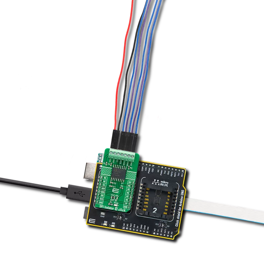
SPI Isolator 4 Click
Dev. board
Flip&Click PIC32MZ
Compiler
NECTO Studio
MCU
PIC32MZ2048EFH100
This isolator allows you to bridge the gap between systems with different ground references, ensuring that data is transmitted accurately and without disruptions
A
A
Hardware Overview
How does it work?
SPI Isolator 4 Click is based on the ADuM341E, a quad-channel digital isolator optimized for a serial peripheral interface from Analog Devices. This isolation component provides outstanding performance characteristics by combining high-speed and CMOS technology. It uses a high-frequency carrier to transmit data across the isolation barrier using iCoupler chip scale transformer coils separated by layers of polyimide isolation. Its data channels are independent and available in various configurations with a withstand voltage rating of 5kVrms. Using an ON/OFF keying (OOK) technique and the differential architecture, the ADuM341E has a very low propagation delay and high speed. It operates
with the external supply voltage ranging from 2.25V to 5.5V, providing compatibility with lower voltage systems and enabling voltage translation functionality across the isolation barrier. The ADuM341E architecture is designed for high common-mode transient (CMTI) immunity and high immunity to electrical noise and magnetic interference. Unlike other optocoupler alternatives, DC correctness is ensured without input logic transitions. Two different fail-safe options are available, by which the outputs go into a predetermined state when the input power supply is not applied or the inputs are disabled. SPI Isolator 4 Click communicates with an MCU using the SPI serial interface with a maximum data rate
of 100Mbps. This Click board™ also comes with an SDO line enable control pin, labeled as EN1, routed on the PWM pin of the mikroBUS™ socket. When EN1 is in a high logic state, the SDO line is enabled, and when EN1 is in a low logic state, the SDO line is disabled to the high-Z state. This Click board™ can operate with either 3.3V or 5V logic voltage levels selected via the VCC SEL jumper. This way, both 3.3V and 5V capable MCUs can use the communication lines properly. Also, this Click board™ comes equipped with a library containing easy-to-use functions and an example code that can be used as a reference for further development.


Features overview
Development board
Flip&Click PIC32MZ is a compact development board designed as a complete solution that brings the flexibility of add-on Click boards™ to your favorite microcontroller, making it a perfect starter kit for implementing your ideas. It comes with an onboard 32-bit PIC32MZ microcontroller, the PIC32MZ2048EFH100 from Microchip, four mikroBUS™ sockets for Click board™ connectivity, two USB connectors, LED indicators, buttons, debugger/programmer connectors, and two headers compatible with Arduino-UNO pinout. Thanks to innovative manufacturing technology,
it allows you to build gadgets with unique functionalities and features quickly. Each part of the Flip&Click PIC32MZ development kit contains the components necessary for the most efficient operation of the same board. In addition, there is the possibility of choosing the Flip&Click PIC32MZ programming method, using the chipKIT bootloader (Arduino-style development environment) or our USB HID bootloader using mikroC, mikroBasic, and mikroPascal for PIC32. This kit includes a clean and regulated power supply block through the USB Type-C (USB-C) connector. All communication
methods that mikroBUS™ itself supports are on this board, including the well-established mikroBUS™ socket, user-configurable buttons, and LED indicators. Flip&Click PIC32MZ development kit allows you to create a new application in minutes. Natively supported by Mikroe software tools, it covers many aspects of prototyping thanks to a considerable number of different Click boards™ (over a thousand boards), the number of which is growing every day.

Microcontroller Overview
MCU Card / MCU

Architecture
PIC32
MCU Memory (KB)
2048
Silicon Vendor
Microchip
Pin count
100
RAM (Bytes)
524288
Used MCU Pins
mikroBUS™ mapper
Take a closer look
Click board™ Schematic

Step by step
Project assembly

Start by selecting your development board and Click board™. Begin with the Flip&Click PIC32MZ as your development board.


Track your results in real time
Application Output
1. Application Output - In Debug mode, the 'Application Output' window enables real-time data monitoring, offering direct insight into execution results. Ensure proper data display by configuring the environment correctly using the provided tutorial.

2. UART Terminal - Use the UART Terminal to monitor data transmission via a USB to UART converter, allowing direct communication between the Click board™ and your development system. Configure the baud rate and other serial settings according to your project's requirements to ensure proper functionality. For step-by-step setup instructions, refer to the provided tutorial.

3. Plot Output - The Plot feature offers a powerful way to visualize real-time sensor data, enabling trend analysis, debugging, and comparison of multiple data points. To set it up correctly, follow the provided tutorial, which includes a step-by-step example of using the Plot feature to display Click board™ readings. To use the Plot feature in your code, use the function: plot(*insert_graph_name*, variable_name);. This is a general format, and it is up to the user to replace 'insert_graph_name' with the actual graph name and 'variable_name' with the parameter to be displayed.

Software Support
Library Description
This library contains API for SPI Isolator 4 Click driver.
Key functions:
spiisolator4_generic_write- SPI Isolator 4 data writing functionspiisolator4_generic_read- SPI Isolator 4 data reading function
Open Source
Code example
The complete application code and a ready-to-use project are available through the NECTO Studio Package Manager for direct installation in the NECTO Studio. The application code can also be found on the MIKROE GitHub account.
/*!
 * @file main.c
 * @brief SPIIsolator4 Click example
 *
 * # Description
 * This library contains API for the SPI Isolator 4 Click driver.
 * This demo application shows an example of an SPI Isolator 4 Click wired
 * to the nvSRAM 4 Click for reading Device ID.
 *
 * The demo application is composed of two sections :
 *
 * ## Application Init
 * Initialization of SPI module and log UART.
 * After driver initialization, the app sets the default configuration.
 *
 * ## Application Task
 * This is an example that shows the use of an SPI Isolator 4 Click board™.
 * Logs Device ID of the nvSRAM 4 Click wired to the SPI Isolator 4 board™.
 * Results are being sent to the Usart Terminal where you can track their changes.
 *
 * ## Additional Function
 * - static void get_device_id ( void )
 *
 * @author Mikroe Team
 *
 */

#include "board.h"
#include "log.h"
#include "spiisolator4.h"

static spiisolator4_t spiisolator4;
static log_t logger;
static uint32_t device_id;

static void get_device_id ( void ) {
    uint8_t rx_data[ 4 ];

    spiisolator4_generic_read( &spiisolator4, 0x9F, &rx_data[ 0 ], 4 );

    device_id = rx_data[ 0 ];
    device_id <<= 8;
    device_id |= rx_data[ 1 ];
    device_id <<= 8;
    device_id |= rx_data[ 2 ];
    device_id <<= 8;
    device_id |= rx_data[ 3 ];
}

void application_init ( void )
{
    log_cfg_t log_cfg;                    /**< Logger config object. */
    spiisolator4_cfg_t spiisolator4_cfg;  /**< Click config object. */

    /**
     * Logger initialization.
     * Default baud rate: 115200
     * Default log level: LOG_LEVEL_DEBUG
     * @note If USB_UART_RX and USB_UART_TX
     * are defined as HAL_PIN_NC, you will
     * need to define them manually for log to work.
     * See @b LOG_MAP_USB_UART macro definition for detailed explanation.
     */
    LOG_MAP_USB_UART( log_cfg );
    log_init( &logger, &log_cfg );
    log_info( &logger, " Application Init " );

    // Click initialization.

    spiisolator4_cfg_setup( &spiisolator4_cfg );
    SPIISOLATOR4_MAP_MIKROBUS( spiisolator4_cfg, MIKROBUS_1 );
    err_t init_flag  = spiisolator4_init( &spiisolator4, &spiisolator4_cfg );
    if ( SPI_MASTER_ERROR == init_flag )
    {
        log_error( &logger, " Application Init Error. " );
        log_info( &logger, " Please, run program again... " );

        for ( ; ; );
    }

    spiisolator4_default_cfg ( &spiisolator4 );
    log_info( &logger, " Application Task " );
    log_printf( &logger, "--------------------------\r\n" );
    Delay_ms ( 100 );
}

void application_task ( void )
{
    get_device_id( );
    log_printf( &logger, "  Device ID : 0x%.8LX\r\n", device_id );
    log_printf( &logger, "--------------------------\r\n" );
    Delay_ms ( 1000 );
}

int main ( void )
{
    /* Do not remove this line or clock might not be set correctly. */
    #ifdef PREINIT_SUPPORTED
    preinit();
    #endif

    application_init( );

    for ( ; ; )
    {
        application_task( );
    }

    return 0;
}

// ------------------------------------------------------------------------ END
Additional Support
Resources
Category:SPI