Capture the essence of your environment with HDC1080 and PIC32MZ2048EFH100
Measuring more than just temperature and humidity

Published Nov 08, 2023
Click board™
Temp&Hum 11 Click
Dev. board
Flip&Click PIC32MZ
Compiler
NECTO Studio
MCU
PIC32MZ2048EFH100
The future of climate control is here, and we invite you to be part of it today with our advanced technology.
A
A
Hardware Overview
How does it work?
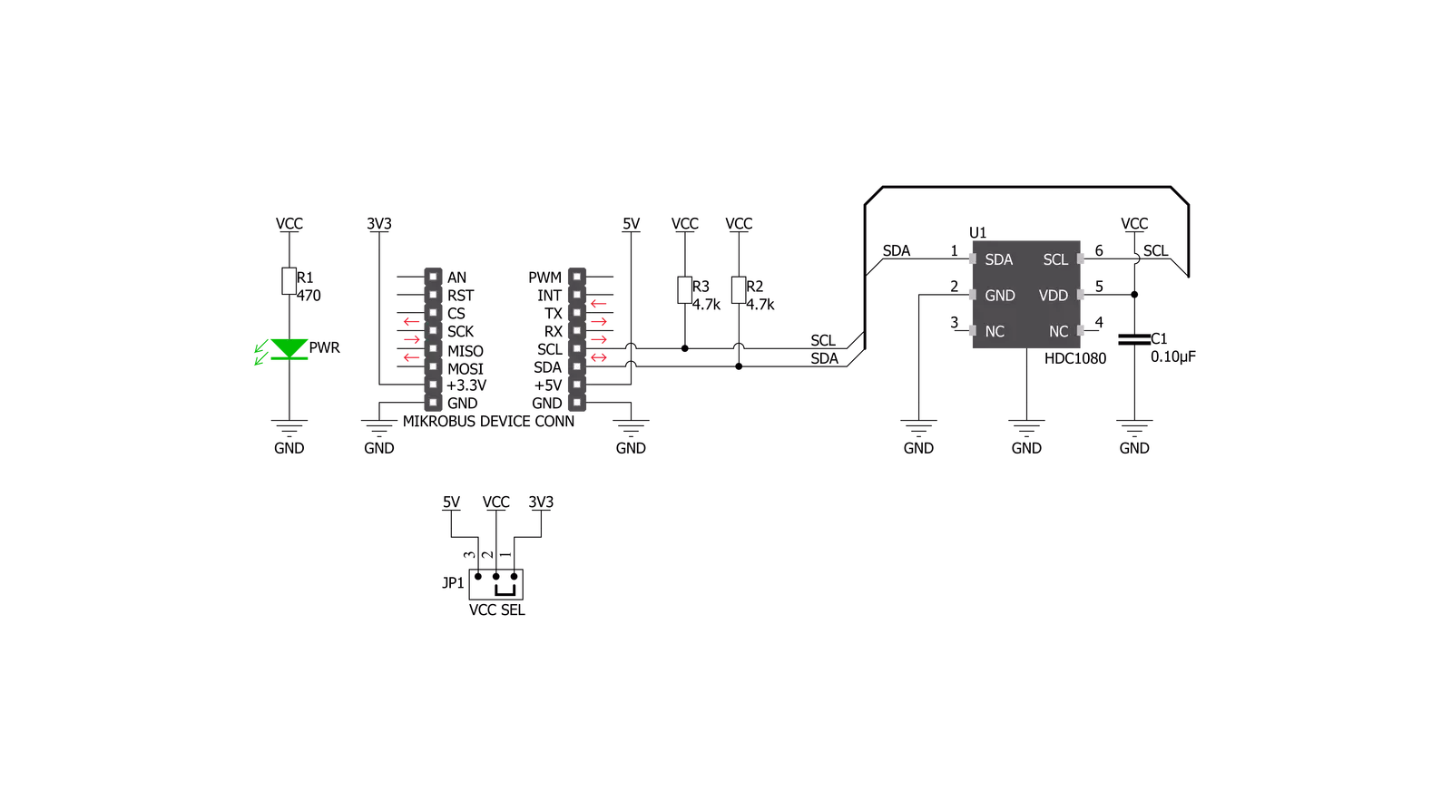
Temp&Hum 11 Click is based on the HDC1080, a low power humidity and temperature digital sensor from Texas Instruments. This sensor is factory calibrated to ±2% relative humidity and ±0.2°C temperature accuracy. It has an integrated heating element that is used to evaporate condensation, protecting the sensor that way. This heating element can be simply activated by setting a bit in the appropriate register. In the case when the heater is powered on, the typical current consumption is about 90mA. Internally, two sensors are connected to the 14-bit ADC section, which can be set to sample measurements with the resolution of 8, 11 or 14 bits, based on the measurement (integration) time. The OTP memory holds the calibration coefficients that are applied to the measured value and the results are stored on the output registers, in the MSB/LSB format. These values
are then used in formulas found in the HDC1080 datasheet so that the final temperature or relative humidity data can be calculated. HDC1080 IC is a very low power consuming device and it can work in two modes: sleep and active (measurement) mode. The device enters the sleep the mode as soon as possible, in order to save power. This makes the HDC1080 suitable to be used for battery-powered applications. In these applications, the HDC1080 can spend most of the time in the sleep mode that has a typical current consumption in the magnitude of nanoamperes. The measurement is triggered after the command is sent over the I2C interface. As soon as the single measurement is finished, the device falls back to a sleep mode. The host should wait for the acquisition to be completed before reading the output registers. However, the Click board™ is
supported by a library of mikroSDK compatible functions, which simplify the development. The heating element can be used to reduce the offset which is a common problem for most RH sensors. It also helps with the condensation, evaporating the excess moisture. The current consumption is increased when the heater is on. It can be enabled by configuring the appropriate register, but it won't be actually activated until a measurement is triggered. Therefore, to increase its temperature, measurement frequency should be increased. The Click board™ can be interfaced with both 3.3V and 5V MCUs without the need for any external components. Thanks to the HDC1080 and its support for a wide supply voltage range, the Click board™ can be simply used with any MCU that supports I2C communication.

Features overview
Development board
Flip&Click PIC32MZ is a compact development board designed as a complete solution that brings the flexibility of add-on Click boards™ to your favorite microcontroller, making it a perfect starter kit for implementing your ideas. It comes with an onboard 32-bit PIC32MZ microcontroller, the PIC32MZ2048EFH100 from Microchip, four mikroBUS™ sockets for Click board™ connectivity, two USB connectors, LED indicators, buttons, debugger/programmer connectors, and two headers compatible with Arduino-UNO pinout. Thanks to innovative manufacturing technology,
it allows you to build gadgets with unique functionalities and features quickly. Each part of the Flip&Click PIC32MZ development kit contains the components necessary for the most efficient operation of the same board. In addition, there is the possibility of choosing the Flip&Click PIC32MZ programming method, using the chipKIT bootloader (Arduino-style development environment) or our USB HID bootloader using mikroC, mikroBasic, and mikroPascal for PIC32. This kit includes a clean and regulated power supply block through the USB Type-C (USB-C) connector. All communication
methods that mikroBUS™ itself supports are on this board, including the well-established mikroBUS™ socket, user-configurable buttons, and LED indicators. Flip&Click PIC32MZ development kit allows you to create a new application in minutes. Natively supported by Mikroe software tools, it covers many aspects of prototyping thanks to a considerable number of different Click boards™ (over a thousand boards), the number of which is growing every day.

Microcontroller Overview
MCU Card / MCU

Architecture
PIC32
MCU Memory (KB)
2048
Silicon Vendor
Microchip
Pin count
100
RAM (Bytes)
524288
Used MCU Pins
mikroBUS™ mapper
Take a closer look
Click board™ Schematic
Step by step
Project assembly

Start by selecting your development board and Click board™. Begin with the Flip&Click PIC32MZ as your development board.


Track your results in real time
Application Output
1. Application Output - In Debug mode, the 'Application Output' window enables real-time data monitoring, offering direct insight into execution results. Ensure proper data display by configuring the environment correctly using the provided tutorial.

2. UART Terminal - Use the UART Terminal to monitor data transmission via a USB to UART converter, allowing direct communication between the Click board™ and your development system. Configure the baud rate and other serial settings according to your project's requirements to ensure proper functionality. For step-by-step setup instructions, refer to the provided tutorial.

3. Plot Output - The Plot feature offers a powerful way to visualize real-time sensor data, enabling trend analysis, debugging, and comparison of multiple data points. To set it up correctly, follow the provided tutorial, which includes a step-by-step example of using the Plot feature to display Click board™ readings. To use the Plot feature in your code, use the function: plot(*insert_graph_name*, variable_name);. This is a general format, and it is up to the user to replace 'insert_graph_name' with the actual graph name and 'variable_name' with the parameter to be displayed.

Software Support
Library Description
This library contains API for Temp&Hum 11 Click driver.
Key functions:
temphum11_get_temperature- This function reads temperature data in desired unit.temphum11_get_humidity- This function reads relative huminidy datatemphum11_read_data- This function reads data from the desired register.
Open Source
Code example
The complete application code and a ready-to-use project are available through the NECTO Studio Package Manager for direct installation in the NECTO Studio. The application code can also be found on the MIKROE GitHub account.
/*!
 * \file
 * \brief TempHum11 Click example
 *
 * # Description
 * This Click has two sensors which can be set to sample measurements with the resolution
 * of 8, 11 or 14 bits, based on the measurement time. Calibration coefficients that are applied
 * to the measured value and the results are stored in the MSB/LSB format, on the output registers.
 * These values are then used in formulas so that the final temperature or relative humidity data can be calculated.
 *
 * The demo application is composed of two sections :
 *
 * ## Application Init
 * Initializes driver init, test comunication and configuration chip for measurement.
 *
 * ## Application Task
 * Reads Temperature and Humidity data. This data logs to USBUART every 1500ms.
 *
 *
 * \author MikroE Team
 *
 */
// ------------------------------------------------------------------- INCLUDES

#include "board.h"
#include "log.h"
#include "temphum11.h"

// ------------------------------------------------------------------ VARIABLES

static temphum11_t temphum11;
static log_t logger;

static float temperature;
static float humidity;

// ------------------------------------------------------ APPLICATION FUNCTIONS

void application_init ( void )
{
    log_cfg_t log_cfg;
    temphum11_cfg_t cfg;

    /**
     * Logger initialization.
     * Default baud rate: 115200
     * Default log level: LOG_LEVEL_DEBUG
     * @note If USB_UART_RX and USB_UART_TX
     * are defined as HAL_PIN_NC, you will
     * need to define them manually for log to work.
     * See @b LOG_MAP_USB_UART macro definition for detailed explanation.
     */
    LOG_MAP_USB_UART( log_cfg );
    log_init( &logger, &log_cfg );
    log_info( &logger, "---- Application Init ----" );

    //  Click initialization.

    temphum11_cfg_setup( &cfg );
    TEMPHUM11_MAP_MIKROBUS( cfg, MIKROBUS_1 );
    temphum11_init( &temphum11, &cfg );

    // Test comunication

    if ( temphum11_read_data( &temphum11, TEMPHUM11_REG_DEVICE_ID ) == TEMPHUM11_DEVICE_ID )
    {
        log_printf( &logger, "--- Comunication OK!!! ---\r\n" );
    }
    else
    {
        log_printf( &logger, "--- Comunication ERROR!!! ---\r\n" );
        for ( ; ; );
    }

    temphum11_default_cfg( &temphum11 );
    log_printf( &logger, "--- Start measurement --- \r\n" );
    Delay_ms ( 500 );
}

void application_task ( void )
{
    temperature = temphum11_get_temperature( &temphum11, TEMPHUM11_TEMP_IN_CELSIUS );

    log_printf( &logger, " Temperature : %.2f\r\n", temperature );

    humidity = temphum11_get_humidity( &temphum11 );

    log_printf( &logger, " Humidity :  %.2f\r\n", humidity );

    log_printf( &logger, "-----------------\r\n" );
    Delay_ms ( 1000 );
    Delay_ms ( 500 );
}

int main ( void )
{
    /* Do not remove this line or clock might not be set correctly. */
    #ifdef PREINIT_SUPPORTED
    preinit();
    #endif

    application_init( );

    for ( ; ; )
    {
        application_task( );
    }

    return 0;
}


// ------------------------------------------------------------------------ END


