Experience the next generation of networking with nRF9160 and PIC32MZ2048EFH100
Step into connectivity's future with LTE
Published Sep 02, 2023
Click board™
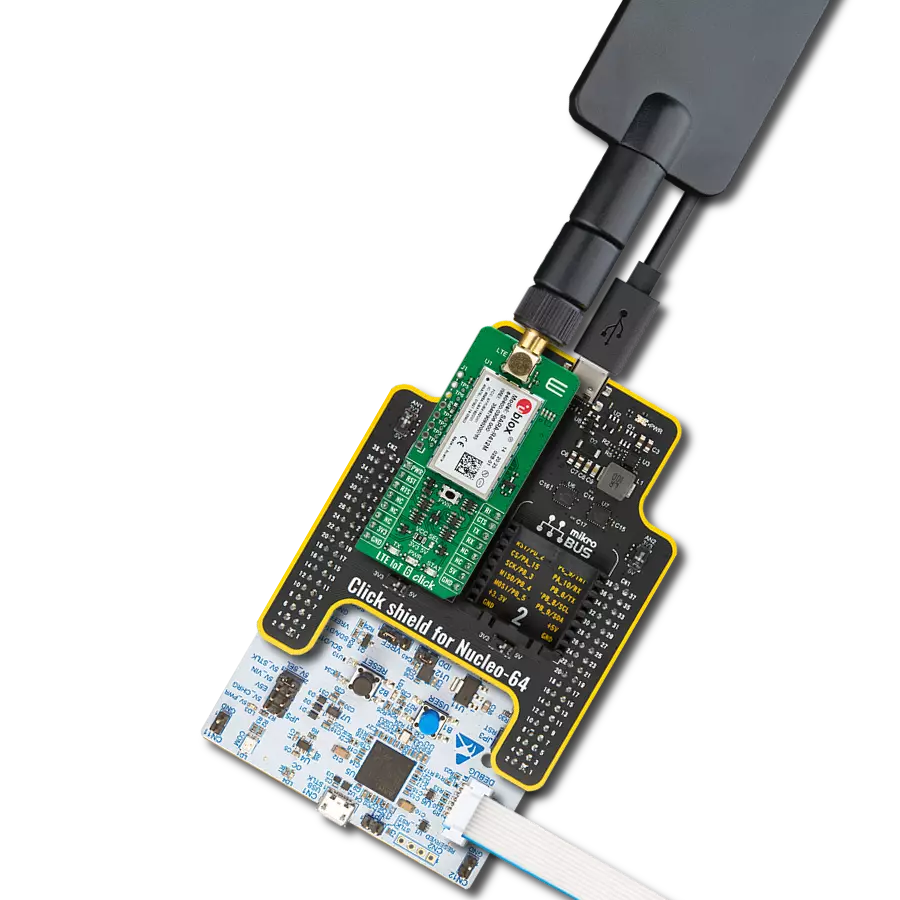
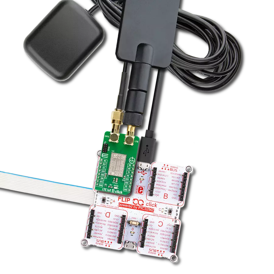
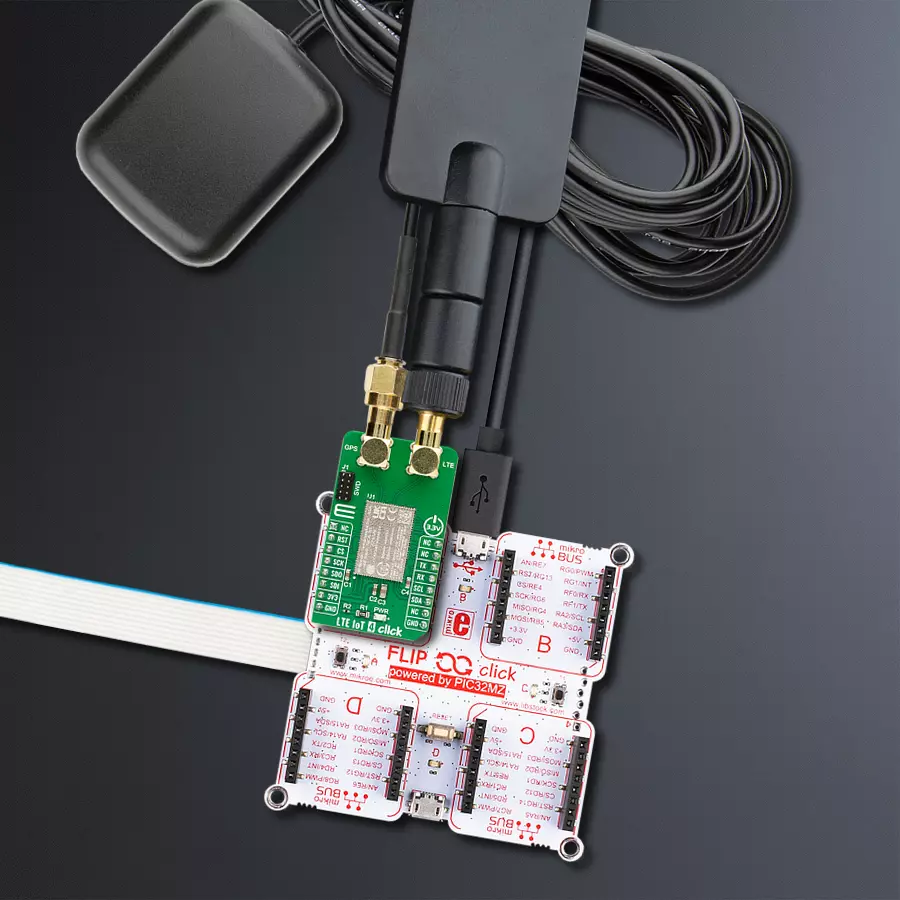
LTE IoT 4 Click
Dev. board
Flip&Click PIC32MZ
Compiler
NECTO Studio
MCU
PIC32MZ2048EFH100
Step into the world where connectivity meets intelligence with our LTE excellence. By embracing our solution, you ensure that your IoT ventures are backed by a robust, seamless, and future-forward network.
A
A
Hardware Overview
How does it work?
LTE IoT 4 Click is based on the nRF9160, a compact, highly-integrated System-in-Package (SiP) with integrated ARM® Cortex®-M33 processor, multimode LTE-M/ NB-IoT modem, RF front end (RFFE), GPS, and power management from Nordic Semiconductor. ARM® Cortex®-M33 processor is supported by 1MB of Flash and 256KB RAM memory with advanced security features, like Arm CryptoCell, that enhance security by offering cryptographic and security resources to help protect your IoT applications from attack threats. It also has built-in assisted GPS suitable for tracking applications that combine location data from the Cloud with GPS satellite to allow remote monitoring of the device's position. The nRF9160 is certified to operate in the most important regions, networks, and LTE bands worldwide. The nRF9160 is designed to take full advantage of the energy efficiency of the LTE-M and NB-IoT standards. It supports the PSM and eDRX power-saving modes, enabling the nRF9160 to sleep longer. At the left
side of this Click board™, there is an additional header labeled as SWD, which offers full support of debugging and programming capabilities through the serial wire debug (SWD) interface (SWDIO, SWCLK, and SWO). LTE IoT 4 Click communicates with MCU using the UART interface as its default communication protocol with the option for the users to use other interfaces, such as SPI and I2C if they want to configure the module and write the library by themselves using these protocols. It also can be reset through the Hardware Reset pin, labeled as RST on the mikroBUS™ socket, by putting this pin in a logic low state. The GPS functionality in the SiP firmware is not currently supported. However, users can develop their FW using Nordic's SDK and the nRF Connect SDK and update the SiP using the SWD interface. LTE IoT 4 Click communicates with MCU using the UART interface as its default communication protocol with the option for the users to use other interfaces, such as SPI and I2C if they want to configure the
module and write the library by themselves using these protocols. It also can be reset through the Hardware Reset pin, labeled as RST on the mikroBUS™ socket, by putting this pin in a logic low state. The LTE modem integrates a flexible transceiver with a frequency range of 700 to 2200 MHz. Also, it possesses two SMA antenna connectors with an impedance of 50Ω labeled as GPS and LTE, used for connecting the appropriate antenna MIKROE offers, like LTE Flat Rotation Antenna and Active GPS Antenna. Besides those SMA connectors, this Click board™ has a micro-SIM card slot that provides multiple connections and interface options. This Click board™ can be operated only with a 3.3V logic voltage level. The board must perform appropriate logic voltage level conversion before using MCUs with different logic levels. Also, it comes equipped with a library containing functions and an example code that can be used as a reference for further development.

Features overview
Development board
Flip&Click PIC32MZ is a compact development board designed as a complete solution that brings the flexibility of add-on Click boards™ to your favorite microcontroller, making it a perfect starter kit for implementing your ideas. It comes with an onboard 32-bit PIC32MZ microcontroller, the PIC32MZ2048EFH100 from Microchip, four mikroBUS™ sockets for Click board™ connectivity, two USB connectors, LED indicators, buttons, debugger/programmer connectors, and two headers compatible with Arduino-UNO pinout. Thanks to innovative manufacturing technology,
it allows you to build gadgets with unique functionalities and features quickly. Each part of the Flip&Click PIC32MZ development kit contains the components necessary for the most efficient operation of the same board. In addition, there is the possibility of choosing the Flip&Click PIC32MZ programming method, using the chipKIT bootloader (Arduino-style development environment) or our USB HID bootloader using mikroC, mikroBasic, and mikroPascal for PIC32. This kit includes a clean and regulated power supply block through the USB Type-C (USB-C) connector. All communication
methods that mikroBUS™ itself supports are on this board, including the well-established mikroBUS™ socket, user-configurable buttons, and LED indicators. Flip&Click PIC32MZ development kit allows you to create a new application in minutes. Natively supported by Mikroe software tools, it covers many aspects of prototyping thanks to a considerable number of different Click boards™ (over a thousand boards), the number of which is growing every day.

Microcontroller Overview
MCU Card / MCU

Architecture
PIC32
MCU Memory (KB)
2048
Silicon Vendor
Microchip
Pin count
100
RAM (Bytes)
524288
Used MCU Pins
mikroBUS™ mapper
Take a closer look
Click board™ Schematic

Step by step
Project assembly

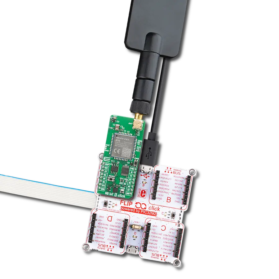
Start by selecting your development board and Click board™. Begin with the Flip&Click PIC32MZ as your development board.


Software Support
Library Description
This library contains API for LTE IoT 4 Click driver.
Key functions:
lteiot4_set_rst- Sets state of the rst pin settinglteiot4_send_cmd- Send command functionlteiot4_set_sim_apn- Set sim card APN
Open Source
Code example
The complete application code and a ready-to-use project are available through the NECTO Studio Package Manager for direct installation in the NECTO Studio. The application code can also be found on the MIKROE GitHub account.
/*!
* @file main.c
* @brief LTE IoT 4 Click Example.
*
* # Description
* This example reads and processes data from LTE IoT 4 Clicks.
*
* The demo application is composed of two sections :
*
* ## Application Init
* Initializes driver and wake-up module.
*
* ## Application Task
* Reads the received data and parses it.
*
* ## Additional Function
* - static void lteiot4_clear_app_buf ( void )
* - static void lteiot4_error_check( err_t error_flag )
* - static void lteiot4_log_app_buf ( void )
* - static void lteiot4_check_connection( void )
* - static err_t lteiot4_rsp_check ( void )
* - static err_t lteiot4_process ( void )
*
* *note:*
* In order for the example to work,
user needs to set the phone number and sim apn to which he wants to send an SMS
* Enter valid data for the following macros: SIM_APN.
* E.g.
SIM_APN "vip.mobile"
*
* @author Luka Filipovic
*
*/
#include "board.h"
#include "log.h"
#include "lteiot4.h"
#define APP_OK 0
#define APP_ERROR_DRIVER -1
#define APP_ERROR_OVERFLOW -2
#define APP_ERROR_TIMEOUT -3
#define RSP_OK "OK"
#define RSP_ERROR "ERROR"
#define SIM_APN "" // Set valid SIM APN
#define PROCESS_BUFFER_SIZE 500
#define WAIT_FOR_CONNECTION 0
#define CONNECTED_TO_NETWORK 1
static lteiot4_t lteiot4;
static log_t logger;
static char app_buf[ PROCESS_BUFFER_SIZE ] = { 0 };
static int32_t app_buf_len = 0;
static int32_t app_buf_cnt = 0;
static uint8_t app_connection_status = WAIT_FOR_CONNECTION;
static err_t app_error_flag;
/**
* @brief LTE IoT 4 clearing application buffer.
* @details This function clears memory of application buffer and reset it's length and counter.
* @note None.
*/
static void lteiot4_clear_app_buf ( void );
/**
* @brief LTE IoT 4 data reading function.
* @details This function reads data from device and concatenates data to application buffer.
*
* @return @li @c 0 - Read some data.
* @li @c -1 - Nothing is read.
* @li @c -2 - Application buffer overflow.
*
* See #err_t definition for detailed explanation.
* @note None.
*/
static err_t lteiot4_process ( void );
/**
* @brief LTE IoT 4 check for errors.
* @details This function checks for different types of errors and logs them on UART.
* @note None.
*/
static void lteiot4_error_check( err_t error_flag );
/**
* @brief LTE IoT 4 logs application buffer.
* @details This function logs data from application buffer.
* @note None.
*/
static void lteiot4_log_app_buf ( void );
/**
* @brief LTE IoT 4 response check.
* @details This function checks for response and returns the status of response.
*
* @return application status.
* See #err_t definition for detailed explanation.
* @note None.
*/
static err_t lteiot4_rsp_check ( void );
/**
* @brief LTE IoT 4 check connection.
* @details This function checks connection to the network and
* logs that status to UART.
*
* @note None.
*/
static void lteiot4_check_connection( void );
void application_init ( void )
{
log_cfg_t log_cfg; /**< Logger config object. */
lteiot4_cfg_t lteiot4_cfg; /**< Click config object. */
/**
* Logger initialization.
* Default baud rate: 115200
* Default log level: LOG_LEVEL_DEBUG
* @note If USB_UART_RX and USB_UART_TX
* are defined as HAL_PIN_NC, you will
* need to define them manually for log to work.
* See @b LOG_MAP_USB_UART macro definition for detailed explanation.
*/
LOG_MAP_USB_UART( log_cfg );
log_init( &logger, &log_cfg );
log_info( &logger, " Application Init " );
Delay_ms ( 1000 );
// Click initialization.
lteiot4_cfg_setup( <eiot4_cfg );
LTEIOT4_MAP_MIKROBUS( lteiot4_cfg, MIKROBUS_1 );
err_t init_flag = lteiot4_init( <eiot4, <eiot4_cfg );
if ( init_flag == UART_ERROR )
{
log_error( &logger, " Application Init Error. " );
log_info( &logger, " Please, run program again... " );
for ( ; ; );
}
log_info( &logger, " Power up device... " );
lteiot4_default_cfg ( <eiot4 );
Delay_ms ( 1000 );
Delay_ms ( 1000 );
Delay_ms ( 1000 );
Delay_ms ( 1000 );
Delay_ms ( 1000 );
lteiot4_process( );
lteiot4_process( );
lteiot4_process( );
lteiot4_clear_app_buf( );
//AT
log_info( &logger, " Communication test " );
lteiot4_send_cmd( <eiot4, LTEIOT4_CMD_AT );
app_error_flag = lteiot4_rsp_check();
lteiot4_error_check( app_error_flag );
Delay_ms ( 500 );
//CGMM
log_info( &logger, " Module version " );
lteiot4_send_cmd( <eiot4, LTEIOT4_CMD_MODULE_VERSION );
app_error_flag = lteiot4_rsp_check();
lteiot4_error_check( app_error_flag );
Delay_ms ( 500 );
//CGMR
log_info( &logger, " FW version " );
lteiot4_send_cmd( <eiot4, LTEIOT4_CMD_FW_VERSION );
app_error_flag = lteiot4_rsp_check();
lteiot4_error_check( app_error_flag );
Delay_ms ( 500 );
//CFUN
log_info( &logger, " Flight mode " );
lteiot4_send_cmd( <eiot4, LTEIOT4_CMD_FLIGHT_MODE );
app_error_flag = lteiot4_rsp_check();
lteiot4_error_check( app_error_flag );
Delay_ms ( 500 );
//XSYSTEMMODE
log_info( &logger, " Enable NB network " );
lteiot4_send_cmd( <eiot4, LTEIOT4_CMD_NBIOT_MODE );
app_error_flag = lteiot4_rsp_check();
lteiot4_error_check( app_error_flag );
Delay_ms ( 500 );
//CIND
log_info( &logger, " Enable service and messages " );
lteiot4_send_cmd( <eiot4, LTEIOT4_CMD_ENABLE_NET_SMS );
app_error_flag = lteiot4_rsp_check();
lteiot4_error_check( app_error_flag );
Delay_ms ( 500 );
//CFUN
log_info( &logger, " Full functionalty mode " );
lteiot4_send_cmd( <eiot4, LTEIOT4_CMD_FULL_FUNCTION );
app_error_flag = lteiot4_rsp_check();
lteiot4_error_check( app_error_flag );
Delay_ms ( 500 );
//CGDCONT
log_info( &logger, " Set APN " );
lteiot4_set_sim_apn( <eiot4, SIM_APN );
app_error_flag = lteiot4_rsp_check();
lteiot4_error_check( app_error_flag );
Delay_ms ( 500 );
//COPS
log_info( &logger, " Set automatic network search " );
lteiot4_send_cmd( <eiot4, LTEIOT4_CMD_AUTO_NET_SRC );
app_error_flag = lteiot4_rsp_check();
lteiot4_error_check( app_error_flag );
Delay_ms ( 500 );
//CEREG
log_info( &logger, " Activate search for network " );
lteiot4_send_cmd( <eiot4, LTEIOT4_CMD_SEARCH_NET );
app_error_flag = lteiot4_rsp_check();
lteiot4_error_check( app_error_flag );
Delay_ms ( 500 );
//CIMI
log_info( &logger, " SIM test " );
lteiot4_send_cmd( <eiot4, LTEIOT4_CMD_SIM_TEST );
app_error_flag = lteiot4_rsp_check();
lteiot4_error_check( app_error_flag );
Delay_ms ( 500 );
app_buf_len = 0;
app_buf_cnt = 0;
app_connection_status = WAIT_FOR_CONNECTION;
log_info( &logger, " Application Task\r\n" );
log_printf( &logger, "-------------------------------\r\n" );
Delay_ms ( 1000 );
Delay_ms ( 1000 );
Delay_ms ( 1000 );
}
void application_task ( void )
{
if ( app_connection_status == WAIT_FOR_CONNECTION )
{
//CEREG
log_info( &logger, " Check connection " );
lteiot4_send_cmd( <eiot4, LTEIOT4_CMD_CHECK_CONNECTION );
app_error_flag = lteiot4_rsp_check();
lteiot4_error_check( app_error_flag );
Delay_ms ( 500 );
//CEREG
log_info( &logger, " Check network status " );
lteiot4_send_cmd( <eiot4, LTEIOT4_CMD_CHECK_REGISTARTION );
app_error_flag = lteiot4_rsp_check();
lteiot4_error_check( app_error_flag );
Delay_ms ( 500 );
//CEREG
log_info( &logger, " Check signal quality " );
lteiot4_send_cmd( <eiot4, LTEIOT4_CMD_SIGNAL_QUALITY );
app_error_flag = lteiot4_rsp_check();
lteiot4_error_check( app_error_flag );
log_printf( &logger, "-------------------------------\r\n" );
Delay_ms ( 1000 );
Delay_ms ( 1000 );
Delay_ms ( 1000 );
Delay_ms ( 1000 );
Delay_ms ( 1000 );
}
else
{
log_info( &logger, "CONNECTED TO NETWORK\r\n" );
log_printf( &logger, "-------------------------------\r\n" );
//CCLK
log_info( &logger, " Set Time " );
lteiot4_send_cmd( <eiot4, LTEIOT4_CMD_SET_DUMMY_CLOCK );
app_error_flag = lteiot4_rsp_check();
lteiot4_error_check( app_error_flag );
log_printf( &logger, "-------------------------------\r\n" );
Delay_ms ( 1000 );
Delay_ms ( 1000 );
Delay_ms ( 1000 );
for(;;)
{
//XTEMP
log_info( &logger, " Check Temperature " );
lteiot4_send_cmd( <eiot4, LTEIOT4_CMD_CHECK_TEMPERATURE );
app_error_flag = lteiot4_rsp_check();
lteiot4_error_check( app_error_flag );
Delay_ms ( 500 );
//CCLK
log_info( &logger, " Check Time " );
lteiot4_send_cmd( <eiot4, LTEIOT4_CMD_CHECK_CLOCK );
app_error_flag = lteiot4_rsp_check();
lteiot4_error_check( app_error_flag );
log_printf( &logger, "-------------------------------\r\n" );
Delay_ms ( 1000 );
Delay_ms ( 1000 );
Delay_ms ( 1000 );
Delay_ms ( 1000 );
Delay_ms ( 1000 );
}
}
}
int main ( void )
{
/* Do not remove this line or clock might not be set correctly. */
#ifdef PREINIT_SUPPORTED
preinit();
#endif
application_init( );
for ( ; ; )
{
application_task( );
}
return 0;
}
static void lteiot4_clear_app_buf ( void )
{
memset( app_buf, 0, app_buf_len );
app_buf_len = 0;
app_buf_cnt = 0;
}
static err_t lteiot4_process ( void )
{
err_t return_flag = APP_ERROR_DRIVER;
int32_t rx_size;
char rx_buff[ PROCESS_BUFFER_SIZE ] = { 0 };
rx_size = lteiot4_generic_read( <eiot4, rx_buff, PROCESS_BUFFER_SIZE );
if ( rx_size > 0 )
{
int32_t buf_cnt = 0;
return_flag = APP_OK;
if ( app_buf_len + rx_size >= PROCESS_BUFFER_SIZE )
{
lteiot4_clear_app_buf( );
return_flag = APP_ERROR_OVERFLOW;
}
else
{
buf_cnt = app_buf_len;
app_buf_len += rx_size;
}
for ( int32_t rx_cnt = 0; rx_cnt < rx_size; rx_cnt++ )
{
if ( rx_buff[ rx_cnt ] != 0 )
{
app_buf[ ( buf_cnt + rx_cnt ) ] = rx_buff[ rx_cnt ];
}
else
{
app_buf_len--;
}
}
}
return return_flag;
}
static err_t lteiot4_rsp_check ( void )
{
uint16_t timeout_cnt = 0;
uint16_t timeout = 5000;
err_t error_flag = lteiot4_process( );
if ( ( error_flag != 0 ) && ( error_flag != -1 ) )
{
return error_flag;
}
while ( ( strstr( app_buf, RSP_OK ) == 0 ) && ( strstr( app_buf, RSP_ERROR ) == 0 ) )
{
error_flag = lteiot4_process( );
if ( ( error_flag != 0 ) && ( error_flag != -1 ) )
{
return error_flag;
}
timeout_cnt++;
if ( timeout_cnt > timeout )
{
lteiot4_clear_app_buf( );
return APP_ERROR_TIMEOUT;
}
Delay_ms ( 1 );
}
lteiot4_check_connection();
lteiot4_log_app_buf();
return APP_OK;
}
static void lteiot4_error_check( err_t error_flag )
{
if ( ( error_flag != 0 ) && ( error_flag != -1 ) )
{
switch ( error_flag )
{
case -2:
log_error( &logger, " Overflow!" );
break;
case -3:
log_error( &logger, " Timeout!" );
break;
default:
break;
}
}
}
static void lteiot4_log_app_buf ( void )
{
for ( int32_t buf_cnt = 0; buf_cnt < app_buf_len; buf_cnt++ )
{
log_printf( &logger, "%c", app_buf[ buf_cnt ] );
}
log_printf( &logger, "\r\n" );
lteiot4_clear_app_buf( );
}
static void lteiot4_check_connection( void )
{
#define CONNECTED "+CGATT: 1"
if ( strstr( app_buf, CONNECTED ) != 0 )
{
app_connection_status = CONNECTED_TO_NETWORK;
}
}
// ------------------------------------------------------------------------ END
Additional Support
Resources
Category:LTE IoT