Control the operation of a brushless motor with STSPIN830 and PIC32MZ2048EFH100
The best motor driver for demanding industrial applications

Published Dec 10, 2023
Click board™
Brushless 13 Click
Dev. board
Flip&Click PIC32MZ
Compiler
NECTO Studio
MCU
PIC32MZ2048EFH100
Manage the speed, direction, and overall performance of a brushless motor by precisely regulating the flow of electrical power
A
A
Hardware Overview
How does it work?
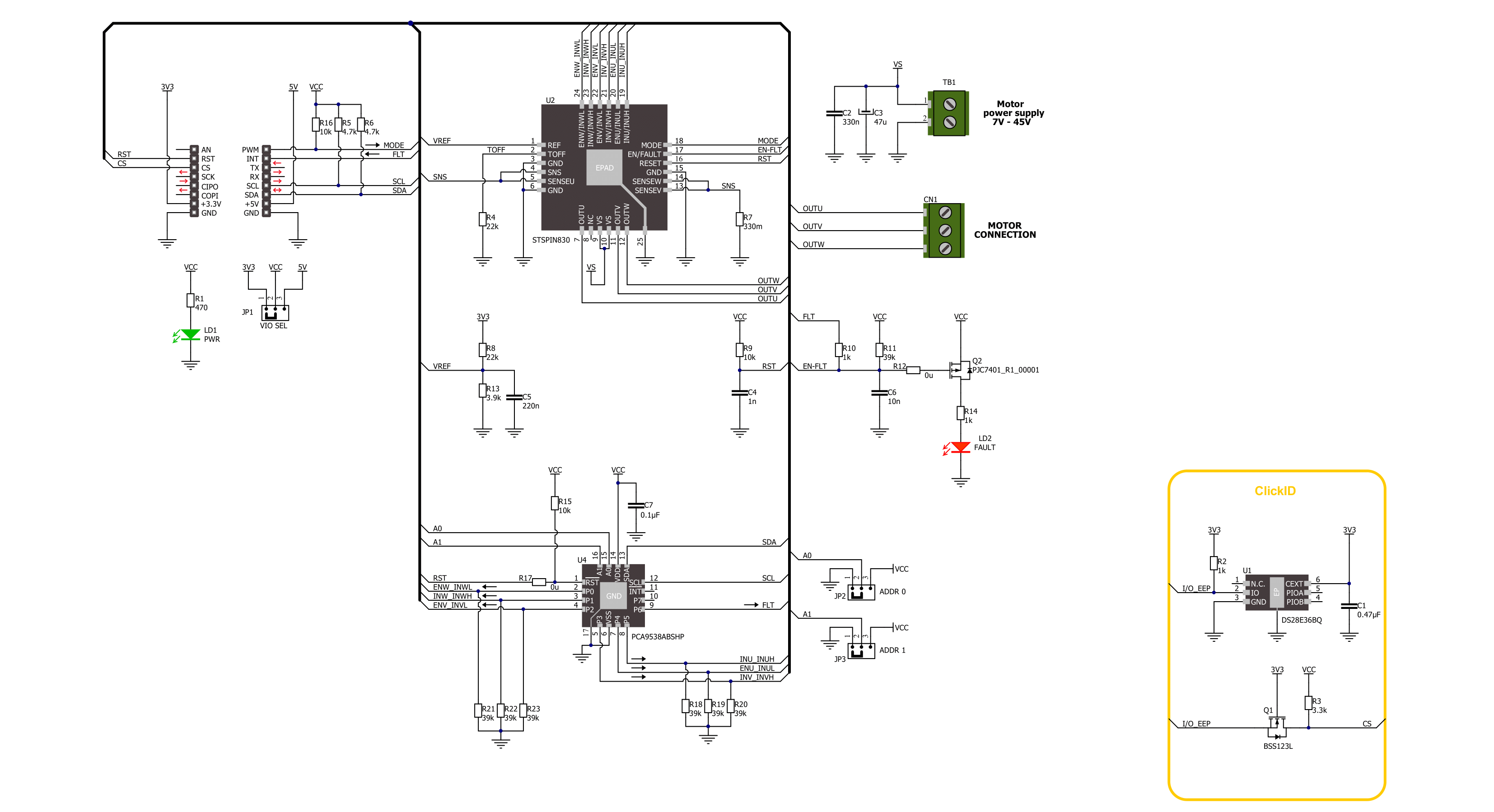
Brushless 13 Click is based on the STSPIN830, a compact and versatile three-phase and three-sense motor driver from STMicroelectronics. The driver features the dedicated mode input, thus allowing you to decide whether to drive it through six inputs, one for each power switch or, more commonly, three PWM direct driving inputs. The driver integrates a complete set of protections for the power stages, such as non-dissipative overcurrent, thermal shutdown, short-circuit, under-voltage lockout, and interlocking. Considering a low standby current consumption, it makes an ideal and bulletproof solution for the new wave of demanding industrial applications. To control all high and low side driver control inputs
of the STSPIN830, Brushless 13 Click features the PCA9538A, a low-voltage 8-bit I2C I/O port with interrupt and reset from NXP. Besides driver control inputs, this I/O port also controls the enable input of the motor driver. The BLDC motor can be connected over the screw terminal, labeled U, V, and W. Additional screw terminal is just aside for connecting an external power supply in a range of 7V up to 45V. Brushless 13 Click uses a standard 2-wire I2C interface of the PCA9538A to communicate with the host MCU, supporting clock frequencies up to 400kHz. The I2C address of the PCA9538A can be set over the ADDR SEL jumpers, with the 0 position selected by default. If a fault condition occurs, the STSPIN830 will pull
the FLT pin to a low logic state, along with the FAULT LED. The RST pin resets the STSPIN830 motor driver. The driver's mode can be set over the MOD pin, with a HIGH logic state for three PWM direct drive inputs. The LOW logic state will allow a driver to drive the motor through six inputs. This Click board™ can operate with either 3.3V or 5V logic voltage levels selected via the VCC SEL jumper. This way, both 3.3V and 5V capable MCUs can use the communication lines properly. Also, this Click board™ comes equipped with a library containing easy-to-use functions and an example code that can be used as a reference for further development.

Features overview
Development board
Flip&Click PIC32MZ is a compact development board designed as a complete solution that brings the flexibility of add-on Click boards™ to your favorite microcontroller, making it a perfect starter kit for implementing your ideas. It comes with an onboard 32-bit PIC32MZ microcontroller, the PIC32MZ2048EFH100 from Microchip, four mikroBUS™ sockets for Click board™ connectivity, two USB connectors, LED indicators, buttons, debugger/programmer connectors, and two headers compatible with Arduino-UNO pinout. Thanks to innovative manufacturing technology,
it allows you to build gadgets with unique functionalities and features quickly. Each part of the Flip&Click PIC32MZ development kit contains the components necessary for the most efficient operation of the same board. In addition, there is the possibility of choosing the Flip&Click PIC32MZ programming method, using the chipKIT bootloader (Arduino-style development environment) or our USB HID bootloader using mikroC, mikroBasic, and mikroPascal for PIC32. This kit includes a clean and regulated power supply block through the USB Type-C (USB-C) connector. All communication
methods that mikroBUS™ itself supports are on this board, including the well-established mikroBUS™ socket, user-configurable buttons, and LED indicators. Flip&Click PIC32MZ development kit allows you to create a new application in minutes. Natively supported by Mikroe software tools, it covers many aspects of prototyping thanks to a considerable number of different Click boards™ (over a thousand boards), the number of which is growing every day.

Microcontroller Overview
MCU Card / MCU

Architecture
PIC32
MCU Memory (KB)
2048
Silicon Vendor
Microchip
Pin count
100
RAM (Bytes)
524288
You complete me!
Accessories
Brushless DC (BLDC) Motor with a Hall sensor represents a high-performance motor from the 42BLF motor series. This motor, wired in a star configuration, boasts a Hall Effect angle of 120°, ensuring precise and reliable performance. With a compact motor length of 47mm and a lightweight design tipping the scales at just 0.29kg, this BLDC motor is engineered to meet your needs. Operating flawlessly at a voltage rating of 24VDC and a speed range of 4000 ± 10% RPM, this motor offers consistent and dependable power. It excels in a normal operational temperature range from -20 to +50°C, maintaining efficiency with a rated current of 1.9A. Also, this product seamlessly integrates with all Brushless Click boards™ and those that require BLDC motors with Hall sensors.

Used MCU Pins
mikroBUS™ mapper
Take a closer look
Click board™ Schematic
Step by step
Project assembly

Start by selecting your development board and Click board™. Begin with the Flip&Click PIC32MZ as your development board.


Software Support
Library Description
This library contains API for Brushless 13 Click driver.
Key functions:
brushless13_set_mode- Brushless 13 set mode pin function.brushless13_get_flt_pin- Brushless 13 get fault pin function.brushless13_drive_motor- Brushless 13 drive motor function.
Open Source
Code example
The complete application code and a ready-to-use project are available through the NECTO Studio Package Manager for direct installation in the NECTO Studio. The application code can also be found on the MIKROE GitHub account.
/*!
 * @file main.c
 * @brief Brushless 13 Click example
 *
 * # Description
 * This example demonstrates the use of the Brushless 13 Click board by driving the
 * motor in both directions at different speeds.
 *
 * The demo application is composed of two sections :
 *
 * ## Application Init
 * Initializes the driver and performs the Click default configuration.
 *
 * ## Application Task
 * Drives the motor in both directions and changes the motor speed approximately every 2 seconds.
 * The driving direction and speed will be displayed on the USB UART.
 *
 * @author Stefan Ilic
 *
 */

#include "board.h"
#include "log.h"
#include "brushless13.h"

static brushless13_t brushless13;
static log_t logger;

void application_init ( void )
{
    log_cfg_t log_cfg;  /**< Logger config object. */
    brushless13_cfg_t brushless13_cfg;  /**< Click config object. */

    /**
     * Logger initialization.
     * Default baud rate: 115200
     * Default log level: LOG_LEVEL_DEBUG
     * @note If USB_UART_RX and USB_UART_TX
     * are defined as HAL_PIN_NC, you will
     * need to define them manually for log to work.
     * See @b LOG_MAP_USB_UART macro definition for detailed explanation.
     */
    LOG_MAP_USB_UART( log_cfg );
    log_init( &logger, &log_cfg );
    log_info( &logger, " Application Init " );

    // Click initialization.
    brushless13_cfg_setup( &brushless13_cfg );
    BRUSHLESS13_MAP_MIKROBUS( brushless13_cfg, MIKROBUS_1 );
    if ( I2C_MASTER_ERROR == brushless13_init( &brushless13, &brushless13_cfg ) )
    {
        log_error( &logger, " Communication init." );
        for ( ; ; );
    }

    if ( BRUSHLESS13_ERROR == brushless13_default_cfg ( &brushless13 ) )
    {
        log_error( &logger, " Default configuration." );
        for ( ; ; );
    }

    log_info( &logger, " Application Task " );
}

void application_task ( void )
{
    log_printf ( &logger, "\r\n Driving motor clockwise \r\n" );
    for ( uint8_t speed = BRUSHLESS13_SPEED_MIN; speed <= BRUSHLESS13_SPEED_MAX; speed += 20 )
    {
        log_printf ( &logger, " Speed gain: %u\r\n", ( uint16_t ) speed );
        if ( BRUSHLESS13_OK != brushless13_drive_motor ( &brushless13, BRUSHLESS13_DIR_CW, speed, 2000 ) )
        {
            log_error ( &logger, " Drive motor " );
        }
    }
    Delay_ms ( 1000 );

    log_printf ( &logger, "\r\n Driving motor counter-clockwise \r\n" );
    for ( uint8_t speed = BRUSHLESS13_SPEED_MIN; speed <= BRUSHLESS13_SPEED_MAX; speed += 20 )
    {
        log_printf ( &logger, " Speed gain: %u\r\n", ( uint16_t ) speed );
        if ( BRUSHLESS13_OK != brushless13_drive_motor ( &brushless13, BRUSHLESS13_DIR_CCW, speed, 2000 ) )
        {
            log_error ( &logger, " Drive motor " );
        }
    }
    Delay_ms ( 1000 );
}

int main ( void )
{
    /* Do not remove this line or clock might not be set correctly. */
    #ifdef PREINIT_SUPPORTED
    preinit();
    #endif

    application_init( );

    for ( ; ; )
    {
        application_task( );
    }

    return 0;
}

// ------------------------------------------------------------------------ END
Additional Support
Resources
Category:Brushless


