Utilize TLE7268 and PIC32MZ2048EFH100 to simplify automotive networking
Streamlined communication: Unleash the potential of LIN transceivers

Published Sep 12, 2023
Click board™
Dual LIN Click
Dev. board
Flip&Click PIC32MZ
Compiler
NECTO Studio
MCU
PIC32MZ2048EFH100
Our LIN transceivers offer unwavering reliability for data exchange in vehicles and industrial systems, contributing to safer and more efficient journeys
A
A
Hardware Overview
How does it work?
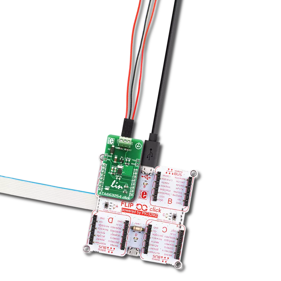
Dual LIN Click is based on the TLE7268, a dual transceiver for the Local Interconnect Network (LIN) from Infineon with integrated wake-up and protection features. The Dual LIN click is designed for in-vehicle networks using data transmission rates up to 20 kbps. Dual LIN click includes two independent transceivers that operate as bus drivers between the protocol controller and physical LIN networks. The Dual LIN click communicates with the MCU by using the UART RX and TX signals. RX and TX signals are also routed to the header on the edge of the click board™ so they can be used independently of the mikroBUS™ socket. Its most important features are the fact that it is a two separate single-wire LIN transceiver bus for transmission rates up to 20 kbps and it is compliant to ISO 17987-4 and LIN Specification 2.2A. The EN1 and EN2 pins are used to enable the functionality of BUS 1 or BUS 2 of the device. When the EN1 pin is set to a HIGH logic level, the BUS 1 of the device is set to work in the normal mode, with the transmission paths from TXD to LIN and from LIN to RXD both active. When
the EN2 pin is set to a HIGH logic level, the BUS 2 of the device is set to work in the normal mode, with the transmission paths from TXD to LIN and from LIN to RXD both active. When the EN1 pin is set to a LOW state, the BUS 1 of the device is put into silent mode, depending on the TX pin state. The EN1 pin has a pull-down resistor, so it is pulled to Ground if it is left afloat. When the EN2 pin is set to a LOW state, the BUS 2 of the device is put into silent mode, depending on the TX pin state. The EN2 pin has a pull-down resistor, so it is pulled to Ground if it is left afloat. The Dual LIN click supports different modes of operation of the two transceivers for minimizing ECU current consumption in low power modes, a common INH output can be used for controlling external circuitry, for example voltage regulators. Based on the Infineon BiCMOS technology. It provides excellent ESD robustness together with very high electromagnetic compliance (EMC). The TLE7268 reaches a very low level of electromagnetic emission (EME) within a broad frequency range and independent from the battery voltage. The
TLE7268 is AEC qualified and tailored to withstand the harsh conditions of the automotive environment. Some of the key features that are incorporated in the TLE7268 are overtemperature protection, undervoltage detection. The Dual LIN click is digital I/O levels compatible with 3.3 V and 5 V microcontrollers, that it is optimized for high electromagnetic compliance (EMC) with very low electromagnetic emission and high immunity to interference. It also features two independent single-wire LIN transceivers in one device and gives out a transmission rate of up to 20 kbps. Given the features included in this transceiver, the Dual LIN click can be used for Body Control Modules (BCM) and Gateway. This Click board™ can operate with either 3.3V or 5V logic voltage levels selected via the VCC SEL jumper. This way, both 3.3V and 5V capable MCUs can use the communication lines properly. Also, this Click board™ comes equipped with a library containing easy-to-use functions and an example code that can be used as a reference for further development.

Features overview
Development board
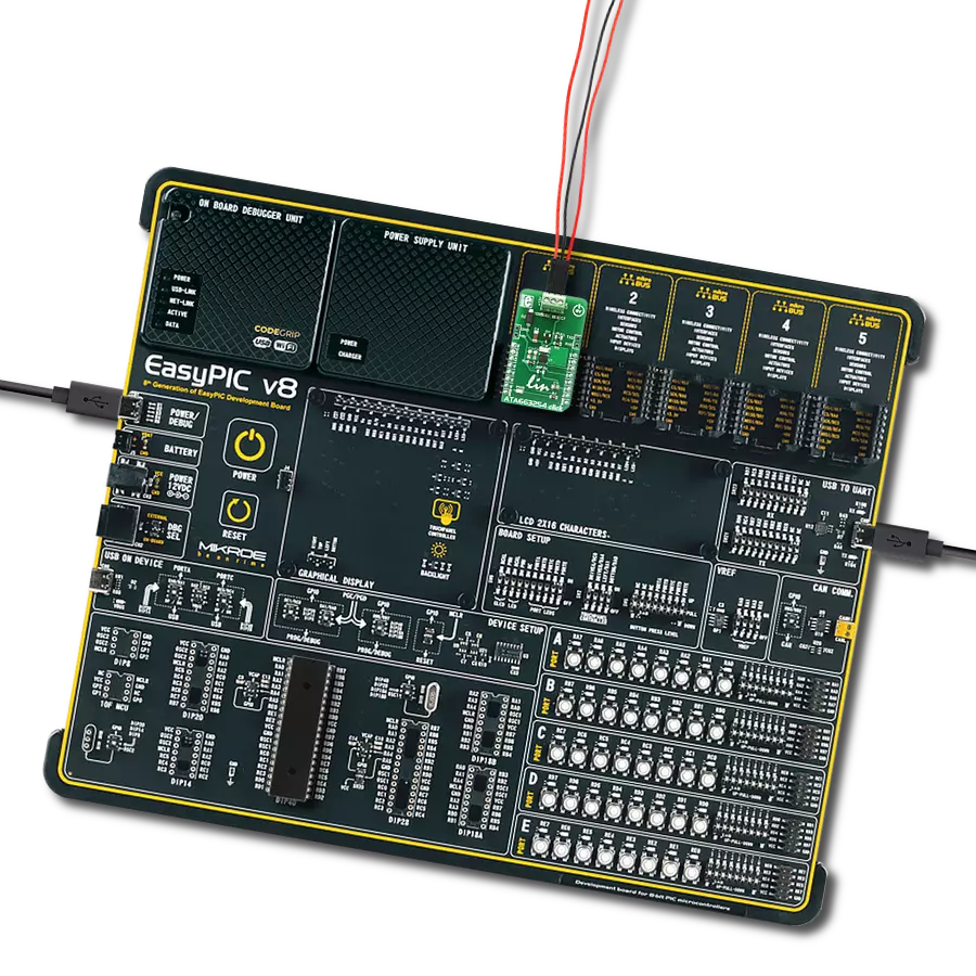
Flip&Click PIC32MZ is a compact development board designed as a complete solution that brings the flexibility of add-on Click boards™ to your favorite microcontroller, making it a perfect starter kit for implementing your ideas. It comes with an onboard 32-bit PIC32MZ microcontroller, the PIC32MZ2048EFH100 from Microchip, four mikroBUS™ sockets for Click board™ connectivity, two USB connectors, LED indicators, buttons, debugger/programmer connectors, and two headers compatible with Arduino-UNO pinout. Thanks to innovative manufacturing technology,
it allows you to build gadgets with unique functionalities and features quickly. Each part of the Flip&Click PIC32MZ development kit contains the components necessary for the most efficient operation of the same board. In addition, there is the possibility of choosing the Flip&Click PIC32MZ programming method, using the chipKIT bootloader (Arduino-style development environment) or our USB HID bootloader using mikroC, mikroBasic, and mikroPascal for PIC32. This kit includes a clean and regulated power supply block through the USB Type-C (USB-C) connector. All communication
methods that mikroBUS™ itself supports are on this board, including the well-established mikroBUS™ socket, user-configurable buttons, and LED indicators. Flip&Click PIC32MZ development kit allows you to create a new application in minutes. Natively supported by Mikroe software tools, it covers many aspects of prototyping thanks to a considerable number of different Click boards™ (over a thousand boards), the number of which is growing every day.

Microcontroller Overview
MCU Card / MCU

Architecture
PIC32
MCU Memory (KB)
2048
Silicon Vendor
Microchip
Pin count
100
RAM (Bytes)
524288
Used MCU Pins
mikroBUS™ mapper
Take a closer look
Click board™ Schematic

Step by step
Project assembly

Start by selecting your development board and Click board™. Begin with the Flip&Click PIC32MZ as your development board.


Software Support
Library Description
This library contains API for Dual LIN Click driver.
Key functions:
duallin_bus1_status- Sets state of RST pinduallin_bus2_status- Sets state of CS pinduallin_send_command- Send command.
Open Source
Code example
The complete application code and a ready-to-use project are available through the NECTO Studio Package Manager for direct installation in the NECTO Studio. The application code can also be found on the MIKROE GitHub account.
/*!
 * \file
 * \brief DualLin Click example
 *
 * # Description
 * This example reads and processes data from Dual LIN Clicks.
 *
 * The demo application is composed of two sections :
 *
 * ## Application Init
 * Initializes driver, and sets bus.
 *
 * ## Application Task
 * Reads the received data.
 *
 * ## Additional Function
 * - duallin_process ( ) - The general process of collecting presponce
 *                                   that sends a module.
 *
 * \author MikroE Team
 *
 */
// ------------------------------------------------------------------- INCLUDES

#include "board.h"
#include "log.h"
#include "duallin.h"
#include "string.h"

#define PROCESS_COUNTER 10
#define PROCESS_RX_BUFFER_SIZE 500

#define TEXT_TO_SEND "MikroE\r\n"

// ------------------------------------------------------------------ VARIABLES

#define DEMO_APP_RECEIVER
// #define DEMO_APP_TRANSMITER

static duallin_t duallin;
static log_t logger;

static char current_rsp_buf[ PROCESS_RX_BUFFER_SIZE ];

// ------------------------------------------------------ APPLICATION FUNCTIONS

void application_init ( void )
{
    log_cfg_t log_cfg;
    duallin_cfg_t cfg;

    /**
     * Logger initialization.
     * Default baud rate: 115200
     * Default log level: LOG_LEVEL_DEBUG
     * @note If USB_UART_RX and USB_UART_TX
     * are defined as HAL_PIN_NC, you will
     * need to define them manually for log to work.
     * See @b LOG_MAP_USB_UART macro definition for detailed explanation.
     */
    LOG_MAP_USB_UART( log_cfg );
    log_init( &logger, &log_cfg );
    log_info( &logger, "---- Application Init ----" );

    //  Click initialization.

    duallin_cfg_setup( &cfg );
    DUALLIN_MAP_MIKROBUS( cfg, MIKROBUS_1 );
    duallin_init( &duallin, &cfg );

    duallin_bus1_status( &duallin, DUALLIN_PIN_STATE_HIGH );
    duallin_bus2_status( &duallin, DUALLIN_PIN_STATE_LOW );
    Delay_ms ( 100 );
}

void application_task ( void )
{
#ifdef DEMO_APP_RECEIVER
    int32_t rsp_size = duallin_generic_read( &duallin, current_rsp_buf, PROCESS_RX_BUFFER_SIZE );
    if ( rsp_size> 0)
    {
        log_printf( &logger, "%s", current_rsp_buf );
    }
#endif

#ifdef DEMO_APP_TRANSMITER
    duallin_send_command( &duallin, TEXT_TO_SEND );
    Delay_ms ( 1000 );
    Delay_ms ( 1000 );
#endif
}

int main ( void )
{
    /* Do not remove this line or clock might not be set correctly. */
    #ifdef PREINIT_SUPPORTED
    preinit();
    #endif

    application_init( );

    for ( ; ; )
    {
        application_task( );
    }

    return 0;
}

// ------------------------------------------------------------------------ END
Additional Support
Resources
Category:LIN