Remotely monitor and collect data from various types of consumption meters with TSS721A and PIC32MZ2048EFH100
Elevate your remote meter reading game

Published Oct 19, 2023
Click board™
M-Bus Slave Click
Dev. board
Flip&Click PIC32MZ
Compiler
NECTO Studio
MCU
PIC32MZ2048EFH100
This advanced solution, featuring the TSS721A transceiver, is designed to seamlessly integrate into Meter-Bus applications, adhering to EN1434-3 standards, and ensuring the highest level of performance and compatibility
A
A
Hardware Overview
How does it work?
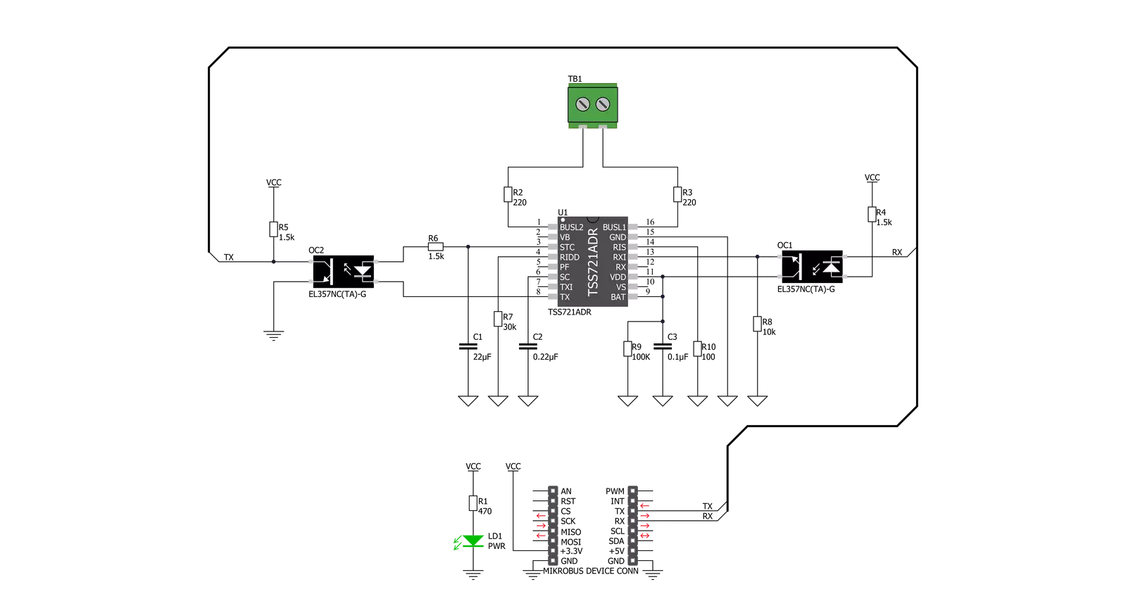
M-Bus Slave Click is based on the TSS721A, a single-chip transceiver developed for Meter-Bus standard (EN1434-3) applications from Texas Instruments. The connection to the bus is polarity independent and serves as a slave node in the system. M-Bus Slave Click has full galvanic isolation with optocouplers to improve the reliability of the whole circuit. The circuit is supplied by the master via the bus. The benefit of the TSS721A in M-Bus slaves is the reduction of the number of components needed, and therefore the cost of slaves. Apart from the transmission and reception of data by the M-Bus specification, this IC also provides translation from and to the operating voltage of the microprocessor to which it is connected, to be able to communicate with it. The communication can take place at baudrates
from 300 to 9600 Baud. Additional features include integrated protection against reversed polarity, a constant 3.3V power supply for the microprocessor, and the prompt indication of failure of the bus voltage. M-Bus is a bus system used for the remote reading of gas, water, heat, electricity, etc. It also supports various sensors and actuators. This is a cost-optimized bus for the transfer of energy consumption data since it is made for communication on only two wires. M-Bus can be used in the industry, but also, it’s convenient to be used in private households. By the standard, M-Bus master can read up to 250 slave devices. They can be meters, water, electrical, or gas meters. You can also use M-bus in applications like alarm systems, flexible illumination installations, heating control, etc. It
can monitor different consumption meters, and it can monitor any leakage. One of the biggest advantages of M-Bus are that all data reading is accomplished remotely. It is a very simple protocol – it uses only two wires, and it uses power supply from the users which are connected to the wire, and reading errors are minimal. Also, reading is very fast. Further processing is very easy since the received data is presented in a machine readable form. There are no special cables – you can use a telephone cable. With that one cable, you can attach all the meters in the housing with all the meters individually addressable. This way you can have control over each consumption meter while using only one connection cable.


Features overview
Development board
Flip&Click PIC32MZ is a compact development board designed as a complete solution that brings the flexibility of add-on Click boards™ to your favorite microcontroller, making it a perfect starter kit for implementing your ideas. It comes with an onboard 32-bit PIC32MZ microcontroller, the PIC32MZ2048EFH100 from Microchip, four mikroBUS™ sockets for Click board™ connectivity, two USB connectors, LED indicators, buttons, debugger/programmer connectors, and two headers compatible with Arduino-UNO pinout. Thanks to innovative manufacturing technology,
it allows you to build gadgets with unique functionalities and features quickly. Each part of the Flip&Click PIC32MZ development kit contains the components necessary for the most efficient operation of the same board. In addition, there is the possibility of choosing the Flip&Click PIC32MZ programming method, using the chipKIT bootloader (Arduino-style development environment) or our USB HID bootloader using mikroC, mikroBasic, and mikroPascal for PIC32. This kit includes a clean and regulated power supply block through the USB Type-C (USB-C) connector. All communication
methods that mikroBUS™ itself supports are on this board, including the well-established mikroBUS™ socket, user-configurable buttons, and LED indicators. Flip&Click PIC32MZ development kit allows you to create a new application in minutes. Natively supported by Mikroe software tools, it covers many aspects of prototyping thanks to a considerable number of different Click boards™ (over a thousand boards), the number of which is growing every day.

Microcontroller Overview
MCU Card / MCU

Architecture
PIC32
MCU Memory (KB)
2048
Silicon Vendor
Microchip
Pin count
100
RAM (Bytes)
524288
Used MCU Pins
mikroBUS™ mapper
Take a closer look
Click board™ Schematic
Step by step
Project assembly

Start by selecting your development board and Click board™. Begin with the Flip&Click PIC32MZ as your development board.


Software Support
Library Description
This library contains API for M-Bus Slave Click driver.
Key functions:
mbusslave_generic_write- Generic write function.mbusslave_generic_read- Generic read function.
Open Source
Code example
The complete application code and a ready-to-use project are available through the NECTO Studio Package Manager for direct installation in the NECTO Studio. The application code can also be found on the MIKROE GitHub account.
/*!
 * \file
 * \brief MBusSlave Click example
 *
 * # Description
 * This example reads and processes data from M-Bus Slave Clicks.
 *
 * The demo application is composed of two sections :
 *
 * ## Application Init
 * Initializes the driver.
 *
 * ## Application Task
 * Depending on the selected mode, it reads all the received data or sends the desired message
 * every 2 seconds.
 *
 * ## Additional Function
 * - mbusslave_process ( ) - The general process of collecting the received data.
 *
 * \author MikroE Team
 *
 */
// ------------------------------------------------------------------- INCLUDES

#include "board.h"
#include "log.h"
#include "mbusslave.h"
#include "string.h"

#define PROCESS_RX_BUFFER_SIZE 500

#define TEXT_TO_SEND "MikroE - M-Bus Slave Click board\r\n"

#define DEMO_APP_RECEIVER
// #define DEMO_APP_TRANSMITTER

// ------------------------------------------------------------------ VARIABLES

static mbusslave_t mbusslave;
static log_t logger;

// ------------------------------------------------------- ADDITIONAL FUNCTIONS

static void mbusslave_process ( void )
{
    int32_t rsp_size;

    char uart_rx_buffer[ PROCESS_RX_BUFFER_SIZE ] = { 0 };
    uint8_t check_buf_cnt;

    rsp_size = mbusslave_generic_read( &mbusslave, uart_rx_buffer, PROCESS_RX_BUFFER_SIZE );

    if ( rsp_size > 0 )
    {
        for ( uint8_t cnt = 0; cnt < rsp_size; cnt++ )
        {
            log_printf( &logger, "%c", uart_rx_buffer[ cnt ] );
            if ( uart_rx_buffer[ cnt ] == '\n' )
            {
                log_printf( &logger, "--------------------------------\r\n" );
            }
        }
    }
}

// ------------------------------------------------------ APPLICATION FUNCTIONS

void application_init ( void )
{
    log_cfg_t log_cfg;
    mbusslave_cfg_t cfg;

    /**
     * Logger initialization.
     * Default baud rate: 115200
     * Default log level: LOG_LEVEL_DEBUG
     * @note If USB_UART_RX and USB_UART_TX
     * are defined as HAL_PIN_NC, you will
     * need to define them manually for log to work.
     * See @b LOG_MAP_USB_UART macro definition for detailed explanation.
     */
    LOG_MAP_USB_UART( log_cfg );
    log_init( &logger, &log_cfg );
    log_info( &logger, "---- Application Init ----" );
    Delay_ms ( 100 );

    //  Click initialization.

    mbusslave_cfg_setup( &cfg );
    MBUSSLAVE_MAP_MIKROBUS( cfg, MIKROBUS_1 );
    mbusslave_init( &mbusslave, &cfg );
    Delay_ms ( 100 );
}

void application_task ( void )
{
#ifdef DEMO_APP_RECEIVER
    mbusslave_process( );
#endif

#ifdef DEMO_APP_TRANSMITTER
    mbusslave_generic_write( &mbusslave, TEXT_TO_SEND, strlen( TEXT_TO_SEND ) );
    log_info( &logger, "---- Data sent ----" );
    Delay_ms ( 1000 );
    Delay_ms ( 1000 );
#endif
}

int main ( void )
{
    /* Do not remove this line or clock might not be set correctly. */
    #ifdef PREINIT_SUPPORTED
    preinit();
    #endif

    application_init( );

    for ( ; ; )
    {
        application_task( );
    }

    return 0;
}

// ------------------------------------------------------------------------ END
Additional Support
Resources
Category:RS232


