Measure how bright the ambient light is in a given environment with PD15-22C/TR8 and STM32F405RG
Manage and adjust lighting systems based on the surrounding light conditions

Published Jan 31, 2024
Click board™
Light Click
Dev. board
SparkFun MicroMod mikroBUS Carrier Board
Compiler
NECTO Studio
MCU
STM32F405RG
High-speed and highly sensitive photodiode specifically designed to detect light in both the visible and infrared spectrum
A
A
Hardware Overview
How does it work?
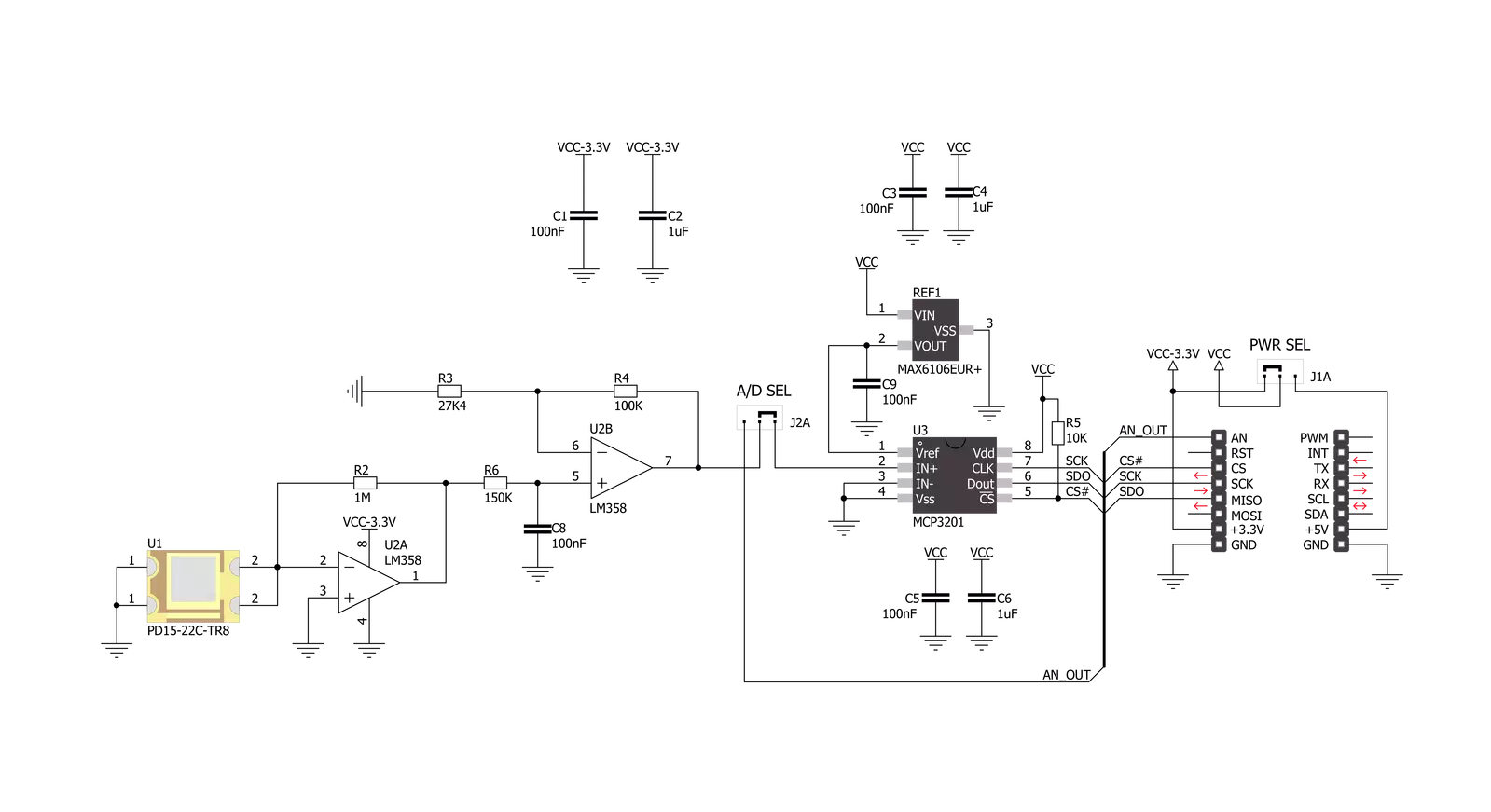
Light Click is based on the PD15-22C/TR8, a high-speed, high-sensitive PIN photodiode from Everlight Electronics, effectively measuring ambient light intensity. This Click board™ is composed of a spectrometric photodiode to a visible and infrared emitting diode with a spectral range from 400 to 1100nm, an amplifier circuit, and an ADC to process the output signal in analog or digital form. The PD15-22C/TR8 has a fast response time with excellent responsivity close to the human eyes' response. It has stable performance over a wide temperature and voltage range and high
photosensitivity (940nm peak sensitivity) across various light sources suitable to sense the amount of the present ambient light. As mentioned, the output of the PD15-22C/TR8, in addition to the signal amplification by the operational amplifier LM358, can be converted to a digital value using MCP3201, a successive approximation A/D converter with a 12-bit resolution from Microchip using a 3-wire SPI compatible interface and a reference voltage set by MAX6106. Apart from the digital signal processing, the output of the PD15-22C/TR8 can be sent directly to an analog pin of
the mikroBUS™ socket labeled as AN. Selection can be performed by onboard SMD jumper labeled as OUTPUT, placing it in an appropriate position marked as AN or ADC. This Click board™ can operate with either 3.3V or 5V logic voltage levels selected via the I/O level jumper. This way, both 3.3V and 5V capable MCUs can use the communication lines properly. However, the Click board™ comes equipped with a library containing easy-to-use functions and an example code that can be used, as a reference, for further development.

Features overview
Development board
SparkFun MicroMod mikroBUS Carrier board takes advantage of the MicroMod, Qwiic, and mikroBUS™ ecosystems making it easy to prototype with each combined rapidly. The MicroMod M.2 socket and mikroBUS™ 8-pin header allow users to experiment with any processor board in the MicroMod ecosystem and any Click board™ in the mikroBUS™ ecosystem,
respectively. This board also features two Qwiic connectors to seamlessly integrate hundreds of Qwiic sensors and accessories into your project. The mikroBUS™ socket comprises a pair of 8-pin female headers with a standardized pin configuration. The pins consist of three groups of communications pins (SPI, UART, and I2C), six additional pins (PWM, Interrupt, Analog input,
Reset, and Chip select), and two power groups (3.3V and 5V). While a modern USB-C connector makes programming easy, the Carrier Board is also equipped with an MCP73831 single-cell Lithium-Ion/Lithium-Polymer charge IC so you can charge an attached single-cell Li-Po battery. The charge IC receives power from the USB connection and can source up to 450mA to charge an attached battery.

Microcontroller Overview
MCU Card / MCU
Architecture
ARM Cortex-M4
MCU Memory (KB)
1024
Silicon Vendor
STMicroelectronics
Pin count
64
RAM (Bytes)
196608
Used MCU Pins
mikroBUS™ mapper
Take a closer look
Click board™ Schematic
Step by step
Project assembly

Start by selecting your development board and Click board™. Begin with the SparkFun MicroMod mikroBUS Carrier Board as your development board.


Software Support
Library Description
This library contains API for Light Click driver.
Key functions:
light_write_data- Generic write data functionlight_read_data- Generic read data functionlight_calculate_percent- Function calculate percent
Open Source
Code example
The complete application code and a ready-to-use project are available through the NECTO Studio Package Manager for direct installation in the NECTO Studio. The application code can also be found on the MIKROE GitHub account.
/*!
 * \file
 * \brief Light Click example
 *
 * # Description
 * This application return the ambient light intensity.
 *
 * The demo application is composed of two sections :
 *
 * ## Application Init
 * Initialization driver enable's - SPI and start write log.
 *
 * ## Application Task
 * This is a example which demonstrates the use of Light Click board.
 * Measured light intensity and calculate light intensity percent from sensor,
 * results are being sent to the Usart Terminal where you can track their changes.
 * All data logs on usb uart for aproximetly every 100 ms when the data value changes.
 *
 *
 *
 * \author MikroE Team
 *
 */
// ------------------------------------------------------------------- INCLUDES

#include "board.h"
#include "log.h"
#include "light.h"

// ------------------------------------------------------------------ VARIABLES

static light_t light;
static log_t logger;

void application_init ( void )
{
    log_cfg_t log_cfg;
    light_cfg_t cfg;

    /**
     * Logger initialization.
     * Default baud rate: 115200
     * Default log level: LOG_LEVEL_DEBUG
     * @note If USB_UART_RX and USB_UART_TX
     * are defined as HAL_PIN_NC, you will
     * need to define them manually for log to work.
     * See @b LOG_MAP_USB_UART macro definition for detailed explanation.
     */
    LOG_MAP_USB_UART( log_cfg );
    log_init( &logger, &log_cfg );
    log_info( &logger, "---- Application Init ----" );

    //  Click initialization.

    light_cfg_setup( &cfg );
    LIGHT_MAP_MIKROBUS( cfg, MIKROBUS_1 );
    light_init( &light, &cfg );

}

void application_task ( void )
{
    uint16_t light_value;
    uint8_t light_percent;

    light_value = light_read_data( &light );
    light_percent = light_calculate_percent( &light, light_value );

    log_printf( &logger, " Light Intensity : %d \r\n", (uint16_t)light_percent );
    log_printf( &logger, " Light Value     : %d\r\n", light_value );
    Delay_ms ( 1000 );

}

int main ( void )
{
    /* Do not remove this line or clock might not be set correctly. */
    #ifdef PREINIT_SUPPORTED
    preinit();
    #endif

    application_init( );

    for ( ; ; )
    {
        application_task( );
    }

    return 0;
}


// ------------------------------------------------------------------------ END
Additional Support
Resources
Category:Optical


