Achieve reliable load management in automotive power distribution systems with VNF1048F and STM32F103RB
High-side switch controller with intelligent e-fuse protection

Published Oct 24, 2024
Click board™
SolidSwitch 6 Click
Dev. board
Nucleo 64 with STM32F103RB MCU
Compiler
NECTO Studio
MCU
STM32F103RB
Ensure safe and reliable load management in automotive power distribution systems
A
A
Hardware Overview
How does it work?
SolidSwitch 6 Click is based on the VNF1048F, a high-side switch controller for automotive applications from STMicroelectronics. This intelligent controller is designed to drive external MOSFETs in a high-side configuration, making it ideal for 12V, 24V, and 48V power distribution systems. Its key feature is intelligent e-fuse protection, which provides reliable overcurrent protection. It is crucial for automotive environments where safety and performance are paramount, like load management in cars, trucks, and other vehicles. The board operates with an external supply voltage ranging from 6V to 48V, allowing flexibility in power applications, with an integrated VIN green LED indicator showing an active external power supply. At its core, the VNF1048F replaces traditional high-current automotive fuses with an advanced overcurrent protection mechanism capable of detecting and responding to excessive current to protect connected systems. It features an
integrated gate drive that controls an external MOSFET (Q2 STL130N8F7) used for load control. The load connection is made through a VOUT terminal, accompanied by a green LED that indicates active load control. Additionally, SolidSwitch 6 Click integrates an NTC (Negative Temperature Coefficient) resistor, which monitors the external MOSFET's temperature to ensure safe operation. The VNF1048F offers protection features, including battery under-voltage shutdown, configurable external MOSFET desaturation shutdown, and hard short-circuit latch-off. It also protects the device and external MOSFET overheating, automatically shutting down in case of high temperatures. Despite its robust features, SolidSwitch 6 Click boasts a very low standby current, ensuring operation even in power-sensitive applications. The VNF1048F communicates with the host MCU via a 3.3V and 5V CMOS-compatible SPI interface, enabling system protection and
diagnostics. In addition to the SPI interface pins, this board also uses other mikroBUS™ socket pins, such as the DGN pin for diagnostic feedback and the HWL pin, which triggers a state where the registers are locked from writing, enhancing system security and prevent unintended configuration changes. The board also includes an unpopulated header labeled V3, which provides access to the output of the 3.3V internal LDO voltage regulator intended for logic and I/O supply. This Click board™ can operate with either 3.3V or 5V logic voltage levels selected via the VIO SEL jumper. This way, both 3.3V and 5V capable MCUs can use the communication lines properly. Also, this Click board™ comes equipped with a library containing easy-to-use functions and an example code that can be used as a reference for further development.

Features overview
Development board
Nucleo-64 with STM32F103RB MCU offers a cost-effective and adaptable platform for developers to explore new ideas and prototype their designs. This board harnesses the versatility of the STM32 microcontroller, enabling users to select the optimal balance of performance and power consumption for their projects. It accommodates the STM32 microcontroller in the LQFP64 package and includes essential components such as a user LED, which doubles as an ARDUINO® signal, alongside user and reset push-buttons, and a 32.768kHz crystal oscillator for precise timing operations. Designed with expansion and flexibility in mind, the Nucleo-64 board features an ARDUINO® Uno V3 expansion connector and ST morpho extension pin
headers, granting complete access to the STM32's I/Os for comprehensive project integration. Power supply options are adaptable, supporting ST-LINK USB VBUS or external power sources, ensuring adaptability in various development environments. The board also has an on-board ST-LINK debugger/programmer with USB re-enumeration capability, simplifying the programming and debugging process. Moreover, the board is designed to simplify advanced development with its external SMPS for efficient Vcore logic supply, support for USB Device full speed or USB SNK/UFP full speed, and built-in cryptographic features, enhancing both the power efficiency and security of projects. Additional connectivity is
provided through dedicated connectors for external SMPS experimentation, a USB connector for the ST-LINK, and a MIPI® debug connector, expanding the possibilities for hardware interfacing and experimentation. Developers will find extensive support through comprehensive free software libraries and examples, courtesy of the STM32Cube MCU Package. This, combined with compatibility with a wide array of Integrated Development Environments (IDEs), including IAR Embedded Workbench®, MDK-ARM, and STM32CubeIDE, ensures a smooth and efficient development experience, allowing users to fully leverage the capabilities of the Nucleo-64 board in their projects.

Microcontroller Overview
MCU Card / MCU

Architecture
ARM Cortex-M3
MCU Memory (KB)
128
Silicon Vendor
STMicroelectronics
Pin count
64
RAM (Bytes)
20480
You complete me!
Accessories
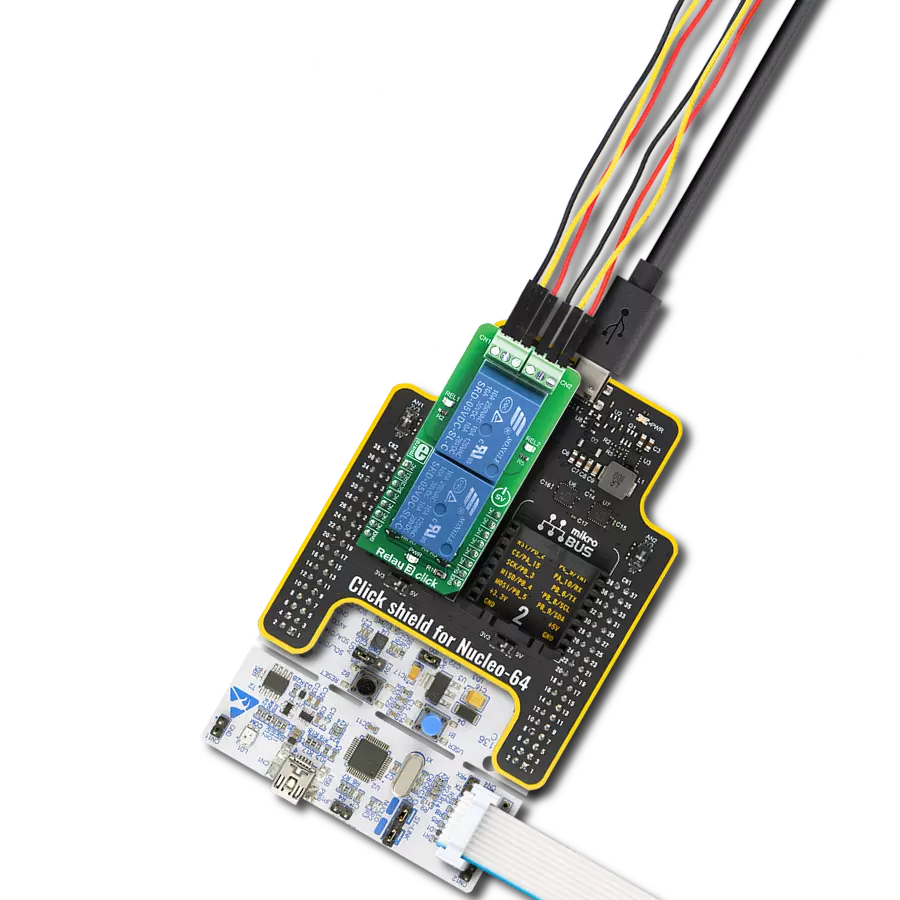
Click Shield for Nucleo-64 comes equipped with two proprietary mikroBUS™ sockets, allowing all the Click board™ devices to be interfaced with the STM32 Nucleo-64 board with no effort. This way, Mikroe allows its users to add any functionality from our ever-growing range of Click boards™, such as WiFi, GSM, GPS, Bluetooth, ZigBee, environmental sensors, LEDs, speech recognition, motor control, movement sensors, and many more. More than 1537 Click boards™, which can be stacked and integrated, are at your disposal. The STM32 Nucleo-64 boards are based on the microcontrollers in 64-pin packages, a 32-bit MCU with an ARM Cortex M4 processor operating at 84MHz, 512Kb Flash, and 96KB SRAM, divided into two regions where the top section represents the ST-Link/V2 debugger and programmer while the bottom section of the board is an actual development board. These boards are controlled and powered conveniently through a USB connection to program and efficiently debug the Nucleo-64 board out of the box, with an additional USB cable connected to the USB mini port on the board. Most of the STM32 microcontroller pins are brought to the IO pins on the left and right edge of the board, which are then connected to two existing mikroBUS™ sockets. This Click Shield also has several switches that perform functions such as selecting the logic levels of analog signals on mikroBUS™ sockets and selecting logic voltage levels of the mikroBUS™ sockets themselves. Besides, the user is offered the possibility of using any Click board™ with the help of existing bidirectional level-shifting voltage translators, regardless of whether the Click board™ operates at a 3.3V or 5V logic voltage level. Once you connect the STM32 Nucleo-64 board with our Click Shield for Nucleo-64, you can access hundreds of Click boards™, working with 3.3V or 5V logic voltage levels.

Wire Jumpers Male to Male (15 cm length, 10pcs) is a set of high-quality jumper wires designed for easy prototyping and testing. Each wire in the set is 15cm long, with male connectors on both ends, allowing an easy connection between components on breadboards or other electronic projects. The set includes ten wires in different colors, providing clear identification and organization in your circuit. These wire jumpers are ideal for DIY projects, setups, and other electronic applications where quick, reliable connections are required.

Used MCU Pins
mikroBUS™ mapper
Take a closer look
Click board™ Schematic

Step by step
Project assembly
Start by selecting your development board and Click board™. Begin with the Nucleo 64 with STM32F103RB MCU as your development board.


Software Support
Library Description
This library contains API for SolidSwitch 6 Click driver.
Key functions:
solidswitch6_get_vout- This function reads the raw ADC value and converts it to a proportional voltage level using the SPI serial interface.solidswitch6_set_control- This function writes control registers to configure the switch controller using the SPI serial interface.solidswitch6_get_device_temp- This function reads the raw ADC value and converts it to device temperature in degrees Celsius using the SPI serial interface.
Open Source
Code example
The complete application code and a ready-to-use project are available through the NECTO Studio Package Manager for direct installation in the NECTO Studio. The application code can also be found on the MIKROE GitHub account.
/*!
 * @file main.c
 * @brief SolidSwitch 6 Click example
 *
 * # Description
 * This library contains API for the SolidSwitch 6 Click driver
 * and demonstrate uses of the high-side switch controller with intelligent fuse protection.
 *
 * The demo application is composed of two sections :
 *
 * ## Application Init
 * The initialization of the SPI module and log UART.
 * After driver initialization, the app sets the default configuration.
 *
 * ## Application Task
 * The demo application reads and displays the device temperature
 * and voltage level of the current sense amplifier, NTC, and output voltage measurement.
 * Results are being sent to the UART Terminal, where you can track their changes.
 *
 * @author Nenad Filipovic
 *
 */

#include "board.h"
#include "log.h"
#include "solidswitch6.h"

static solidswitch6_t solidswitch6;
static log_t logger;

void application_init ( void )
{
    log_cfg_t log_cfg;  /**< Logger config object. */
    solidswitch6_cfg_t solidswitch6_cfg;  /**< Click config object. */

    /**
     * Logger initialization.
     * Default baud rate: 115200
     * Default log level: LOG_LEVEL_DEBUG
     * @note If USB_UART_RX and USB_UART_TX
     * are defined as HAL_PIN_NC, you will
     * need to define them manually for log to work.
     * See @b LOG_MAP_USB_UART macro definition for detailed explanation.
     */
    LOG_MAP_USB_UART( log_cfg );
    log_init( &logger, &log_cfg );
    log_info( &logger, " Application Init " );

    // Click initialization.
    solidswitch6_cfg_setup( &solidswitch6_cfg );
    SOLIDSWITCH6_MAP_MIKROBUS( solidswitch6_cfg, MIKROBUS_1 );
    if ( SPI_MASTER_ERROR == solidswitch6_init( &solidswitch6, &solidswitch6_cfg ) )
    {
        log_error( &logger, " Communication init." );
        for ( ; ; );
    }

    if ( SOLIDSWITCH6_ERROR == solidswitch6_default_cfg ( &solidswitch6 ) )
    {
        log_error( &logger, " Default configuration." );
        for ( ; ; );
    }

    log_info( &logger, " Application Task " );
    log_printf( &logger, " ______________________\r\n" );
    Delay_ms ( 100 );
}

void application_task ( void )
{
    float app_buf = 0;
    if ( SOLIDSWITCH6_OK == solidswitch6_get_device_temp( &solidswitch6, &app_buf ) )
    {
        log_printf( &logger, " Temperature: %.2f [degC]\r\n", app_buf );
        Delay_ms ( 100 );
    }

    if ( SOLIDSWITCH6_OK == solidswitch6_get_vntc( &solidswitch6, &app_buf ) )
    {
        log_printf( &logger, " NTC: %.2f V\r\n", app_buf );
        Delay_ms ( 100 );
    }

    if ( SOLIDSWITCH6_OK == solidswitch6_get_vout( &solidswitch6, &app_buf ) )
    {
        log_printf( &logger, " Vout: %.2f V\r\n", app_buf );
        Delay_ms ( 100 );
    }

    if ( SOLIDSWITCH6_OK == solidswitch6_get_vds( &solidswitch6, &app_buf ) )
    {
        log_printf( &logger, " VDS: %.2f V\r\n", app_buf );
        Delay_ms ( 100 );
    }

    log_printf( &logger, " ______________________\r\n" );
    Delay_ms ( 1000 );
}

int main ( void )
{
    /* Do not remove this line or clock might not be set correctly. */
    #ifdef PREINIT_SUPPORTED
    preinit();
    #endif

    application_init( );

    for ( ; ; )
    {
        application_task( );
    }

    return 0;
}

// ------------------------------------------------------------------------ END
Additional Support
Resources
Category:Relay