Deliver swift and efficient power with BQ25792 and PIC32MZ2048EFM100
Fast, efficient, Li-Ion charging at your fingertips

Published Nov 15, 2023
Click board™
Charger 25 Click
Dev. board
Curiosity PIC32 MZ EF
Compiler
NECTO Studio
MCU
PIC32MZ2048EFM100
Elevate your charging experience with our Li-Ion battery charger, meticulously designed to deliver not just power, but optimized performance and prolonged device life.
A
A
Hardware Overview
How does it work?
Charger 25 Click is based on the BQ25792, a buck-boost battery charger with a dual-input selector and a USB PD3.0 OTG output from Texas Instruments. Additionally, the BQ25792 supports input source detection through D+ and D-, which is compatible with USB 2.0 and USB 3.0 power delivery, non-standard adapters, and high voltage adapters. With dual input source selection, USB OTG support, and an integrated 16-bit multi-channel analog-to-digital converter (ADC), the BQ25792 is a complete charging solution. The ADC monitors the charge current and input/battery/system voltages, the temperature qualification voltage input pin, and the die temperature, the data that can be used in BQ25792’s protection and interrupt systems. Charger 25 Click allows you to select the number of cells (cell count) to be charged and its optimal configuration over the 4-position CELL SEL jumper, where the 1s (1 cell) is set by default. With this feature, not only the cell count will be set, but also the switching frequency, where the values can be found in the table of the BQ25792’s datasheet, according to the used resistors on Charger 25 Click (for 1s, the switching frequency is 1.5MHz). This further sets the default charging current and voltage, which can be later altered depending on the selected cell count in a range from 3V up to 18.8V. The charging current also depends on the
cell count and can be either 1A or 2A. A BATT JST connector connects a battery (or batteries). Another cool feature of Charger 25 Click is the ability to use an external negative temperature coefficient thermistor (NTC) over the appropriate 2-pin header. The charge is suspended when the temperature is out of range. This feature can be enabled over the NTC SEL jumper where the NRM (normal) is set by default. A STAT LED indicator indicates charging in progress, charge complete, Hi-Z mode, charge suspend, and other statuses. The VBUS LED indicates the presence of the voltage on the VBUS rail, which includes both the USB C and a nearby VBUS header. Over the VBUS header, the charger can be supplied over a wide range of input voltages (3.6V – 24V). The charger employs a synchronous buck-boost converter that allows charging the 1s to 4s batteries from a legacy 5V USB input source, HVDCP, and USB-PD power sources. It operates uninterruptedly and continuously in buck, boost, or buck-boost mode, depending on the input-to-system output voltage difference. The converter operates in a proprietary buck-boost mode when the input voltage is close to the system output voltage. The charger output voltage to the system is available over the VSYS terminal. In the absence of the input sources, Charger 25 Click supports the USB
OtG function and can generate an adjustable 2.8V-22V voltage on the USB C connector (and VBUS terminal, too), which complies with the USB PD 3.0 specification. Fast Charging is also supported, as BQ25792 provides D+/D- handshake and is compliant with both USB 2.0 and USB 3.0 PD. Charger 25 Click uses a standard 2-Wire I2C interface to communicate with the host MCU, supporting a clock frequency of up to 1MHz. In addition to the I2C host-controlled charging mode, Charger 25 Click also supports autonomous charging mode. This way, after powering up, the charging is enabled with all default settings and can complete charging without software engagement. The QON pin can be used as a wake-up pin (ship FET enable) or for a system power reset control. The charger interrupts the host MCU over the INT pin, which can be statuses of even 18 events. The charge-enable CE pin can be used to turn off the charger. If connected to a LOW logic, the charger can complete charging autonomously. This Click board™ can be operated only with a 3.3V logic voltage level. The board must perform appropriate logic voltage level conversion before using MCUs with different logic levels. Also, it comes equipped with a library containing functions and an example code that can be used as a reference for further development.

Features overview
Development board
Curiosity PIC32 MZ EF development board is a fully integrated 32-bit development platform featuring the high-performance PIC32MZ EF Series (PIC32MZ2048EFM) that has a 2MB Flash, 512KB RAM, integrated FPU, Crypto accelerator, and excellent connectivity options. It includes an integrated programmer and debugger, requiring no additional hardware. Users can expand
functionality through MIKROE mikroBUS™ Click™ adapter boards, add Ethernet connectivity with the Microchip PHY daughter board, add WiFi connectivity capability using the Microchip expansions boards, and add audio input and output capability with Microchip audio daughter boards. These boards are fully integrated into PIC32’s powerful software framework, MPLAB Harmony,
which provides a flexible and modular interface to application development a rich set of inter-operable software stacks (TCP-IP, USB), and easy-to-use features. The Curiosity PIC32 MZ EF development board offers expansion capabilities making it an excellent choice for a rapid prototyping board in Connectivity, IOT, and general-purpose applications.

Microcontroller Overview
MCU Card / MCU

Architecture
PIC32
MCU Memory (KB)
2048
Silicon Vendor
Microchip
Pin count
100
RAM (Bytes)
524288
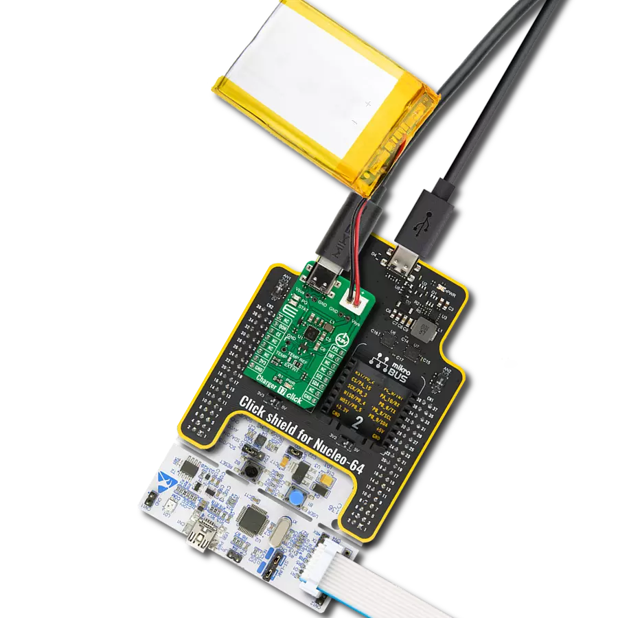
You complete me!
Accessories
Li-Polymer Battery is the ideal solution for devices that demand a dependable and long-lasting power supply while emphasizing mobility. Its compatibility with mikromedia boards ensures easy integration without additional modifications. With a voltage output of 3.7V, the battery meets the standard requirements of many electronic devices. Additionally, boasting a capacity of 2000mAh, it can store a substantial amount of energy, providing sustained power for extended periods. This feature minimizes the need for frequent recharging or replacement. Overall, the Li-Polymer Battery is a reliable and autonomous power source, ideally suited for devices requiring a stable and enduring energy solution. You can find a more extensive choice of Li-Polymer batteries in our offer.

Used MCU Pins
mikroBUS™ mapper
Take a closer look
Click board™ Schematic

Step by step
Project assembly

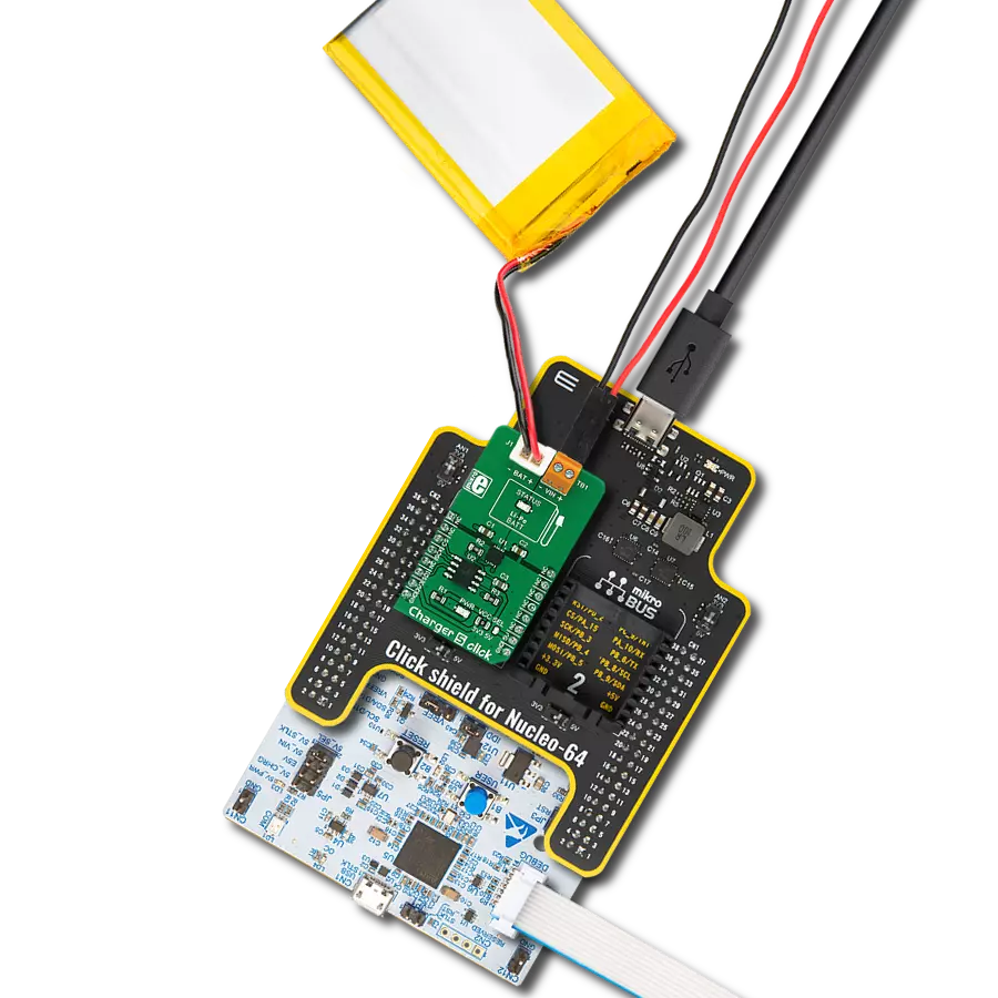
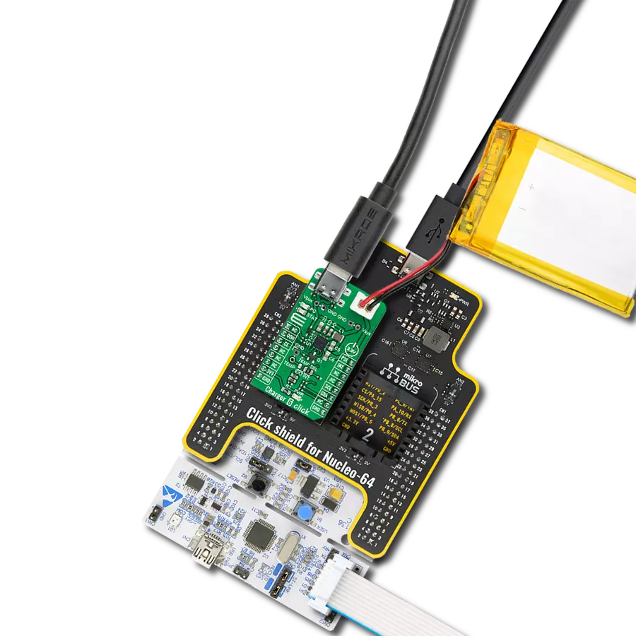
Start by selecting your development board and Click board™. Begin with the Curiosity PIC32 MZ EF as your development board.


Track your results in real time
Application Output
1. Application Output - In Debug mode, the 'Application Output' window enables real-time data monitoring, offering direct insight into execution results. Ensure proper data display by configuring the environment correctly using the provided tutorial.

2. UART Terminal - Use the UART Terminal to monitor data transmission via a USB to UART converter, allowing direct communication between the Click board™ and your development system. Configure the baud rate and other serial settings according to your project's requirements to ensure proper functionality. For step-by-step setup instructions, refer to the provided tutorial.

3. Plot Output - The Plot feature offers a powerful way to visualize real-time sensor data, enabling trend analysis, debugging, and comparison of multiple data points. To set it up correctly, follow the provided tutorial, which includes a step-by-step example of using the Plot feature to display Click board™ readings. To use the Plot feature in your code, use the function: plot(*insert_graph_name*, variable_name);. This is a general format, and it is up to the user to replace 'insert_graph_name' with the actual graph name and 'variable_name' with the parameter to be displayed.

Software Support
Library Description
This library contains API for Charger 25 Click driver.
Key functions:
charger25_get_vbat- Charger 25 get VBAT function.charger25_get_status- Charger 25 get charging status function.charger25_get_vbat_lim- Charger 25 get battery voltage limit function.
Open Source
Code example
The complete application code and a ready-to-use project are available through the NECTO Studio Package Manager for direct installation in the NECTO Studio. The application code can also be found on the MIKROE GitHub account.
/*!
 * @file main.c
 * @brief Charger 25 Click example
 *
 * # Description
 * This example demonstrates the use of Charger 25 Click board™
 * by enabling battery charging and displaying battery voltage and charging status.
 *
 * The demo application is composed of two sections :
 *
 * ## Application Init
 * Initialization of I2C module and log UART.
 * After driver initialization, the app executes a default configuration.
 *
 * ## Application Task
 * The demo application reads and displays the results of the battery voltage,
 * minimal system voltage, battery voltage limit and charging status.
 * Results are being sent to the UART Terminal, where you can track their changes.
 *
 * ## Additional Function
 * - static void charger25_display_status ( void )
 *
 * @author Nenad Filipovic
 *
 */

#include "board.h"
#include "log.h"
#include "charger25.h"

static charger25_t charger25;
static log_t logger;

static charger25_status_t status;

/**
 * @brief Charger 25 displays the status.
 * @details This function displays  the charging status.
 * @note None.
 */
static void charger25_display_status ( void );

void application_init ( void )
{
    log_cfg_t log_cfg;  /**< Logger config object. */
    charger25_cfg_t charger25_cfg;  /**< Click config object. */

    /**
     * Logger initialization.
     * Default baud rate: 115200
     * Default log level: LOG_LEVEL_DEBUG
     * @note If USB_UART_RX and USB_UART_TX
     * are defined as HAL_PIN_NC, you will
     * need to define them manually for log to work.
     * See @b LOG_MAP_USB_UART macro definition for detailed explanation.
     */
    LOG_MAP_USB_UART( log_cfg );
    log_init( &logger, &log_cfg );
    log_info( &logger, " Application Init " );

    // Click initialization.
    charger25_cfg_setup( &charger25_cfg );
    CHARGER25_MAP_MIKROBUS( charger25_cfg, MIKROBUS_1 );
    if ( I2C_MASTER_ERROR == charger25_init( &charger25, &charger25_cfg ) )
    {
        log_error( &logger, " Communication init." );
        for ( ; ; );
    }

    if ( CHARGER25_ERROR == charger25_default_cfg ( &charger25 ) )
    {
        log_error( &logger, " Default configuration." );
        for ( ; ; );
    }

    log_info( &logger, " Application Task " );
    log_printf( &logger, " ----------------\r\n" );
    Delay_ms ( 100 );
}

void application_task ( void )
{
    static uint16_t vtg_data = 0;
    if ( CHARGER25_OK == charger25_get_status ( &charger25, &status ) )
    {
        charger25_display_status( );
    }
    Delay_ms ( 100 );

    if ( CHARGER25_OK == charger25_get_vbat( &charger25, &vtg_data ) )
    {
        log_printf( &logger, " VBAT: %u [mV]\r\n", vtg_data );
    }
    Delay_ms ( 100 );

    if ( CHARGER25_OK == charger25_get_vsys_min( &charger25, &vtg_data ) )
    {
        log_printf( &logger, " VMIN: %u [mV]\r\n", vtg_data );
    }
    Delay_ms ( 100 );

    if ( CHARGER25_OK == charger25_get_vbat_lim( &charger25, &vtg_data ) )
    {
        log_printf( &logger, " VLIM: %u [mV]\r\n", vtg_data );
    }
    log_printf( &logger, " ----------------\r\n" );
    Delay_ms ( 1000 );
}

int main ( void )
{
    /* Do not remove this line or clock might not be set correctly. */
    #ifdef PREINIT_SUPPORTED
    preinit();
    #endif

    application_init( );

    for ( ; ; )
    {
        application_task( );
    }

    return 0;
}

static void charger25_display_status ( void )
{
    log_printf( &logger, " Charge Status: " );
    switch ( status.chg_stat )
    {
        case CHARGER25_CH_STAT_NOT_CHARGING:
        {
            log_printf( &logger, " Not Charging\r\n" );
            break;
        }
        case CHARGER25_CH_STAT_TRICKLE_CHARGE:
        {
            log_printf( &logger, " Trickle Charge\r\n" );
            break;
        }
        case CHARGER25_CH_STAT_PRE_CHARGE:
        {
            log_printf( &logger, "  Pre-charge\r\n" );
            break;
        }
        case CHARGER25_CH_STAT_FAST_CHARGE:
        {
            log_printf( &logger, " Fast charge \r\n" );
            break;
        }
        case CHARGER25_CH_STAT_TAPER_CHARGE:
        {
            log_printf( &logger, " Taper Charge\r\n" );
            break;
        }
        case CHARGER25_CH_STAT_TIMER_ACT_CHARGING:
        {
            log_printf( &logger, " Top-off Timer Active Charging\r\n" );
            break;
        }
        case CHARGER25_CH_STAT_CHARGE_TERMIN_DONE:
        {
            log_printf( &logger, " Charge Termination Done\r\n" );
            break;
        }
        default:
        {
            log_printf( &logger, " Unknown\r\n" );
            break;
        }
    }

    log_printf( &logger, " Battery Status: " );
    if ( status.vbat_present_stat )
    {
        log_printf( &logger, " Battery present\r\n" );
    }
    else
    {
        log_printf( &logger, " No battery\r\n" );
    }
    log_printf( &logger, " - - - - - - - - \r\n" );
}

// ------------------------------------------------------------------------ END