Upgrade your charging game with STBC08 and ATmega328P
Revive your battery life in no time

Published Feb 14, 2024
Click board™
Charger 2 Click
Dev. board
Arduino UNO Rev3
Compiler
NECTO Studio
MCU
ATmega328P
Don't let a dead battery hold you back - integrate a high-quality battery charger into your solution today and always keep it powered up
A
A
Hardware Overview
How does it work?
Charger 2 Click is based on the STBC08, a LiPo/Li-Ion battery charger from STMicroelectronics with the additional monitoring IC onboard. This Click board™, as a whole, offers unpreceded battery charging and monitoring solution for 3.7V LiPo/Li-Ion batteries, with the capacity measurement/gas gauge function, for up to 7000 mAh. It provides measurement data via the I2C interface and two signaling LEDs on the Click board™. It features two dedicated ICs - one for charging the battery and one for monitoring its status. The STBC08, a standalone linear battery charger, performs the charging function, while the STC3100, a battery monitor IC with Coulomb counter/gas gauge, monitors the critical battery parameters. The nominal charging voltage is set to 4.2V. The STBC08 maintains constant current/voltage, providing maximum charging rates while avoiding overheating the IC. The charging current is limited to about 450 mA with the onboard resistor connected to the PROG pin of the IC. It can be further adjusted to 80mA by the onboard potentiometer, connected in series with the PROG pin resistor. The charging is terminated when the battery is nearly fully charged and the charging current drops to 10% of the programmed value. The device automatically restarts the charge cycle when the battery voltage drops
below 4.05 V, maintaining the battery capacity value above 80%. Two LEDs are used to signalize the status of the STBC08 IC: a red LED is used to signalize the ongoing charge process. The green LED signalizes if the charging conditions are nominal and within the specs. It signalizes the validity of the charging voltage value. The battery connector is supplied with the regulated power from the STBC08 IC via the BAT pin. This pin outputs the current and voltage for the battery charging. This connector is mounted on the Click board™ PCB, and it is a standard 2.54mm pitch male pin battery connector used on most MIKROE products for connecting LiPo/Li-Ion batteries. With its lock-on feature, it provides a secure and reliable connection. For monitoring purposes, Charger 2 Click uses the STC3100, a battery monitor IC with Coulomb counter/gas gauge, also from STMicroelectronics. It monitors the voltage and current of the charging battery. It also includes hardware functions to implement a gas gauge for battery charge monitoring based on a programmable A/D converter. This IC can measure a battery capacity of up to 7000mAh. The gas gauge utilizes a sensing resistor of 50mΩ, and the voltage drop on this resistor is sampled by an internal 12-14 bit ADC. These measurements are integrated and stored in an internal
register. The host MCU can read this data via the I2C interface, with its lines routed to the appropriate I2C pins of the mikroBUS™. The resolution of the gas gauge measurement is 0.2 mAh. Battery voltage is measured and converted by a separate ADC, providing readings independent of the gauge section's readings. The battery output voltage is routed to the VIN pin of the STC3100 and can be read via the I2C interface. When the battery voltage drops under the defined threshold, the IC shuts down, and no current is drawn from the connected battery. The measurement resolution is 2.44 mV. The STC3100 also features 32 volatile RAM locations for storing various application-relevant data. The status of this memory is retained as long as there is a power supply to the IC itself. When the power supply is cut off, the content of this memory is lost. The Click board™ is equipped with the SMD jumper labeled as VCCIO SEL, used to choose between 3.3V or 5V operation. However, this Click board™ requires 5V to be present on its 5V mikroBUS™ rail because it is used as the power source for the battery charging IC. VCCIO SEL jumper only allows the logic voltage level to be selected to interface the Click board™ with both 3.3V and 5V MCUs.

Features overview
Development board
Arduino UNO is a versatile microcontroller board built around the ATmega328P chip. It offers extensive connectivity options for various projects, featuring 14 digital input/output pins, six of which are PWM-capable, along with six analog inputs. Its core components include a 16MHz ceramic resonator, a USB connection, a power jack, an
ICSP header, and a reset button, providing everything necessary to power and program the board. The Uno is ready to go, whether connected to a computer via USB or powered by an AC-to-DC adapter or battery. As the first USB Arduino board, it serves as the benchmark for the Arduino platform, with "Uno" symbolizing its status as the
first in a series. This name choice, meaning "one" in Italian, commemorates the launch of Arduino Software (IDE) 1.0. Initially introduced alongside version 1.0 of the Arduino Software (IDE), the Uno has since become the foundational model for subsequent Arduino releases, embodying the platform's evolution.

Microcontroller Overview
MCU Card / MCU

Architecture
AVR
MCU Memory (KB)
32
Silicon Vendor
Microchip
Pin count
28
RAM (Bytes)
2048
You complete me!
Accessories
Click Shield for Arduino UNO has two proprietary mikroBUS™ sockets, allowing all the Click board™ devices to be interfaced with the Arduino UNO board without effort. The Arduino Uno, a microcontroller board based on the ATmega328P, provides an affordable and flexible way for users to try out new concepts and build prototypes with the ATmega328P microcontroller from various combinations of performance, power consumption, and features. The Arduino Uno has 14 digital input/output pins (of which six can be used as PWM outputs), six analog inputs, a 16 MHz ceramic resonator (CSTCE16M0V53-R0), a USB connection, a power jack, an ICSP header, and reset button. Most of the ATmega328P microcontroller pins are brought to the IO pins on the left and right edge of the board, which are then connected to two existing mikroBUS™ sockets. This Click Shield also has several switches that perform functions such as selecting the logic levels of analog signals on mikroBUS™ sockets and selecting logic voltage levels of the mikroBUS™ sockets themselves. Besides, the user is offered the possibility of using any Click board™ with the help of existing bidirectional level-shifting voltage translators, regardless of whether the Click board™ operates at a 3.3V or 5V logic voltage level. Once you connect the Arduino UNO board with our Click Shield for Arduino UNO, you can access hundreds of Click boards™, working with 3.3V or 5V logic voltage levels.

Li-Polymer Battery is the ideal solution for devices that demand a dependable and long-lasting power supply while emphasizing mobility. Its compatibility with mikromedia boards ensures easy integration without additional modifications. With a voltage output of 3.7V, the battery meets the standard requirements of many electronic devices. Additionally, boasting a capacity of 2000mAh, it can store a substantial amount of energy, providing sustained power for extended periods. This feature minimizes the need for frequent recharging or replacement. Overall, the Li-Polymer Battery is a reliable and autonomous power source, ideally suited for devices requiring a stable and enduring energy solution. You can find a more extensive choice of Li-Polymer batteries in our offer.

Used MCU Pins
mikroBUS™ mapper
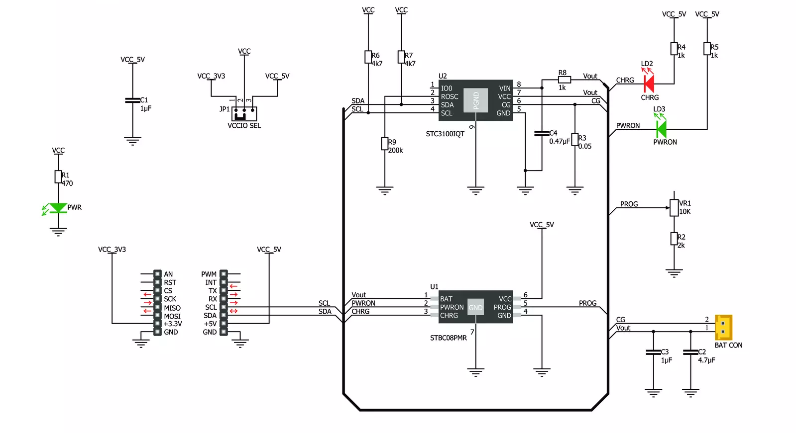
Take a closer look
Click board™ Schematic
Step by step
Project assembly

Start by selecting your development board and Click board™. Begin with the Arduino UNO Rev3 as your development board.


Track your results in real time
Application Output
1. Application Output - In Debug mode, the 'Application Output' window enables real-time data monitoring, offering direct insight into execution results. Ensure proper data display by configuring the environment correctly using the provided tutorial.

2. UART Terminal - Use the UART Terminal to monitor data transmission via a USB to UART converter, allowing direct communication between the Click board™ and your development system. Configure the baud rate and other serial settings according to your project's requirements to ensure proper functionality. For step-by-step setup instructions, refer to the provided tutorial.

3. Plot Output - The Plot feature offers a powerful way to visualize real-time sensor data, enabling trend analysis, debugging, and comparison of multiple data points. To set it up correctly, follow the provided tutorial, which includes a step-by-step example of using the Plot feature to display Click board™ readings. To use the Plot feature in your code, use the function: plot(*insert_graph_name*, variable_name);. This is a general format, and it is up to the user to replace 'insert_graph_name' with the actual graph name and 'variable_name' with the parameter to be displayed.

Software Support
Library Description
This library contains API for Charger 2 Click driver.
Key functions:
charger2_write_reg- This function writes one byte data to the registercharger2_read_data- This function reads the desired data from data registers and converts this data to the appropriate unitcharger2_check_conv_cycle- This function checks is conversion cycle for battery current, or for battery voltage and temperature, finished, and if is not, waits until one of this conversions be finished
Open Source
Code example
The complete application code and a ready-to-use project are available through the NECTO Studio Package Manager for direct installation in the NECTO Studio. The application code can also be found on the MIKROE GitHub account.
/*!
 * \file
 * \brief Charger2 Click example
 *
 * # Description
 * This app charges the battery.
 *
 * The demo application is composed of two sections :
 *
 * ## Application Init
 * Initializes device.
 *
 * ## Application Task
 * Reads the all necessary information for the battery charging status and logs this results on UART.
 * Repeats operation every second.
 * The LED diodes are used to indicate the Vcc presence when this voltage is in operating range, and to show the charging status.
 *
 * \author MikroE Team
 *
 */
// ------------------------------------------------------------------- INCLUDES

#include "board.h"
#include "log.h"
#include "charger2.h"

// ------------------------------------------------------------------ VARIABLES

static charger2_t charger2;
static log_t logger;
uint32_t battery_data;

// ------------------------------------------------------- ADDITIONAL FUNCTIONS

void results_logger ( charger2_t *ctx )
{
    switch ( ctx->unit_mode )
    {
        case CHARGER2_GAS_GAUGE_CHARGE_DATA :
        {
            log_printf( &logger, "Gas gauge charge data is: %u uV.h \r\n", battery_data );
            break;
        }
        case CHARGER2_CONV_NUMBER :
        {
            log_printf( &logger, "Number of conversions is: %u \r\n", battery_data );
            break;
        }
        case CHARGER2_SHUNT_VOLTAGE :
        {
            log_printf( &logger, "Voltage on shunt (CG pin): %u uV \r\n", battery_data );
            break;
        }
        case CHARGER2_BATTERY_VOLTAGE :
        {
            log_printf( &logger, "Battery voltage is: %u mV \r\n", battery_data );
            break;
        }
        case CHARGER2_TEMPERATURE :
        {
            log_printf( &logger, "Temperature is: %u Celsius \r\n", battery_data );
            break;
        }
        case CHARGER2_BATTERY_CURRENT :
        {
            log_printf( &logger, "Battery current is:  %u uA \r\n", battery_data );
            break;
        }
        default :
        {
            break;
        }
    }
}

// ------------------------------------------------------ APPLICATION FUNCTIONS

void application_init ( void )
{
    log_cfg_t log_cfg;
    charger2_cfg_t cfg;

    /**
     * Logger initialization.
     * Default baud rate: 115200
     * Default log level: LOG_LEVEL_DEBUG
     * @note If USB_UART_RX and USB_UART_TX
     * are defined as HAL_PIN_NC, you will
     * need to define them manually for log to work.
     * See @b LOG_MAP_USB_UART macro definition for detailed explanation.
     */
    LOG_MAP_USB_UART( log_cfg );
    log_init( &logger, &log_cfg );
    log_info( &logger, "---- Application Init ----" );

    //  Click initialization.

    charger2_cfg_setup( &cfg );
    CHARGER2_MAP_MIKROBUS( cfg, MIKROBUS_1 );
    charger2_init( &charger2, &cfg );

    Delay_ms ( 500 );

    charger2_reset( &charger2, CHARGER2_RESET_COUNTER_MODE );
    Delay_ms ( 1000 );
    charger2_write_reg( &charger2, CHARGER2_REG_MODE, CHARGER2_AUTO_DETECT | CHARGER2_14_BITS_RESOLUTION | CHARGER2_OPERATING_MODE );
    log_printf( &logger, "Charger 2 is initialized \r\n" );
    log_printf( &logger, "------------------------------ \r\n" );
    Delay_ms ( 300 );
}

void application_task ( void )
{
    charger2_read_data( &charger2, CHARGER2_GAS_GAUGE_CHARGE_DATA, &battery_data );
    results_logger( &charger2 );
    charger2_read_data( &charger2, CHARGER2_CONV_NUMBER, &battery_data );
    results_logger( &charger2 );
    charger2_read_data( &charger2, CHARGER2_SHUNT_VOLTAGE, &battery_data );
    results_logger( &charger2 );
    charger2_read_data( &charger2, CHARGER2_BATTERY_VOLTAGE, &battery_data );
    results_logger( &charger2 );
    charger2_read_data( &charger2, CHARGER2_TEMPERATURE, &battery_data );
    results_logger( &charger2 );
    charger2_read_data( &charger2, CHARGER2_BATTERY_CURRENT, &battery_data );
    results_logger( &charger2 );

    log_printf( &logger, "------------------------------ \r\n" );
    Delay_ms ( 1000 );
}

int main ( void )
{
    /* Do not remove this line or clock might not be set correctly. */
    #ifdef PREINIT_SUPPORTED
    preinit();
    #endif

    application_init( );

    for ( ; ; )
    {
        application_task( );
    }

    return 0;
}

// ------------------------------------------------------------------------ END
Additional Support
Resources
Category:Battery charger


