Bridge the gap between I2C communication and the 1-Wire interface with DS28E17 and PIC32MZ2048EFM100
Simplify wiring and extend the reach of I2C devices across your projects

Published Mar 15, 2024
Click board™
1-Wire I2C click
Dev. board
Curiosity PIC32 MZ EF
Compiler
NECTO Studio
MCU
PIC32MZ2048EFM100
Allow devices that traditionally communicate over I2C to be connected and interact over a 1-Wire interface
A
A
Hardware Overview
How does it work?
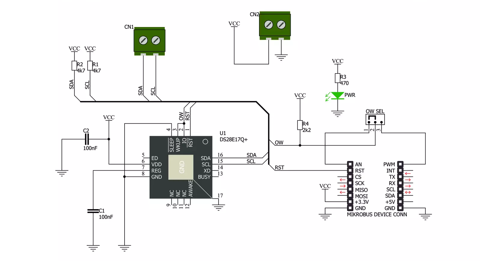
1-Wire I2C Click is based on the DS28E17, a 1-Wire-to-I2C master bridge from Analog Devices. The bridge supports 15Kbps and 77Kbps 1-Wire protocol with packetized I2C data payloads. The factory-programmed unique 64-bit 1-Wire ROM ID provides an unalterable serial number to the end equipment, thus allowing multiple DS8E17 devices to coexist with other devices in a 1-Wire network and be accessed individually without affecting other devices. The 1-Wire I2C Click allows
communication with complex I2C devices, such as displays, ADCs, DACs, sensors, and more. The bridge provides 1-Wire communication with only one I2C device. 1-Wire I2C Click uses the 1-Wire interface as a bridge to the standard 2-Wire I2C interface to communicate with the host MCU. You can choose a One-Wire input pin over the OW SEL jumper, where the OW1 is routed to an analog pin of the mikroBUS™ socket and is set by default. You can also reset the bridge over the RST pin. The I2C
device can be connected over a 4-pin screw terminal. This Click board™ can be operated only with a 3.3V logic voltage level. The board must perform appropriate logic voltage level conversion before using MCUs with different logic levels. Also, this Click board™ comes equipped with a library containing functions and an example code that can be used as a reference for further development.

Features overview
Development board
Curiosity PIC32 MZ EF development board is a fully integrated 32-bit development platform featuring the high-performance PIC32MZ EF Series (PIC32MZ2048EFM) that has a 2MB Flash, 512KB RAM, integrated FPU, Crypto accelerator, and excellent connectivity options. It includes an integrated programmer and debugger, requiring no additional hardware. Users can expand
functionality through MIKROE mikroBUS™ Click™ adapter boards, add Ethernet connectivity with the Microchip PHY daughter board, add WiFi connectivity capability using the Microchip expansions boards, and add audio input and output capability with Microchip audio daughter boards. These boards are fully integrated into PIC32’s powerful software framework, MPLAB Harmony,
which provides a flexible and modular interface to application development a rich set of inter-operable software stacks (TCP-IP, USB), and easy-to-use features. The Curiosity PIC32 MZ EF development board offers expansion capabilities making it an excellent choice for a rapid prototyping board in Connectivity, IOT, and general-purpose applications.

Microcontroller Overview
MCU Card / MCU

Architecture
PIC32
MCU Memory (KB)
2048
Silicon Vendor
Microchip
Pin count
100
RAM (Bytes)
524288
Used MCU Pins
mikroBUS™ mapper
Take a closer look
Click board™ Schematic
Step by step
Project assembly

Start by selecting your development board and Click board™. Begin with the Curiosity PIC32 MZ EF as your development board.


Track your results in real time
Application Output
1. Application Output - In Debug mode, the 'Application Output' window enables real-time data monitoring, offering direct insight into execution results. Ensure proper data display by configuring the environment correctly using the provided tutorial.

2. UART Terminal - Use the UART Terminal to monitor data transmission via a USB to UART converter, allowing direct communication between the Click board™ and your development system. Configure the baud rate and other serial settings according to your project's requirements to ensure proper functionality. For step-by-step setup instructions, refer to the provided tutorial.

3. Plot Output - The Plot feature offers a powerful way to visualize real-time sensor data, enabling trend analysis, debugging, and comparison of multiple data points. To set it up correctly, follow the provided tutorial, which includes a step-by-step example of using the Plot feature to display Click board™ readings. To use the Plot feature in your code, use the function: plot(*insert_graph_name*, variable_name);. This is a general format, and it is up to the user to replace 'insert_graph_name' with the actual graph name and 'variable_name' with the parameter to be displayed.

Software Support
Library Description
This library contains API for 1-Wire I2C Click driver.
Key functions:
c1wirei2c_reset_device- This function resets the device by toggling the RST pin statec1wirei2c_write_data- This function addresses and writes 1-255 bytes to an I2C slave without completing the transaction with a stopc1wirei2c_read_data_stop- This function is used to address and read 1-255 bytes from an I2C slave in one transaction
Open Source
Code example
The complete application code and a ready-to-use project are available through the NECTO Studio Package Manager for direct installation in the NECTO Studio. The application code can also be found on the MIKROE GitHub account.
/*!
* @file main.c
* @brief 1-Wire I2C Click Example.
*
* # Description
* This example demonstrates the use of 1-Wire I2C Click board by reading
* the temperature measurement from connected Thermo 4 Click board.
*
* The demo application is composed of two sections :
*
* ## Application Init
* Initializes the driver and performs the Click default configuration.
*
* ## Application Task
* Reads the temperature measurement from connected Thermo 4 Click board and
* displays the results on the USB UART once per second.
*
* @author Stefan Filipovic
*
*/
#include "board.h"
#include "log.h"
#include "c1wirei2c.h"
// Thermo 4 device settings
#define DEVICE_NAME "Thermo 4 Click"
#define DEVICE_SLAVE_ADDRESS 0x48
#define DEVICE_REG_TEMPERATURE 0x00
#define DEVICE_TEMPERATURE_RES 0.125f
static c1wirei2c_t c1wirei2c;
static log_t logger;
void application_init ( void )
{
log_cfg_t log_cfg; /**< Logger config object. */
c1wirei2c_cfg_t c1wirei2c_cfg; /**< Click config object. */
/**
* Logger initialization.
* Default baud rate: 115200
* Default log level: LOG_LEVEL_DEBUG
* @note If USB_UART_RX and USB_UART_TX
* are defined as HAL_PIN_NC, you will
* need to define them manually for log to work.
* See @b LOG_MAP_USB_UART macro definition for detailed explanation.
*/
LOG_MAP_USB_UART( log_cfg );
log_init( &logger, &log_cfg );
log_info( &logger, " Application Init " );
// Click initialization.
c1wirei2c_cfg_setup( &c1wirei2c_cfg );
C1WIREI2C_MAP_MIKROBUS( c1wirei2c_cfg, MIKROBUS_1 );
if ( ONE_WIRE_ERROR == c1wirei2c_init( &c1wirei2c, &c1wirei2c_cfg ) )
{
log_error( &logger, " Communication init." );
for ( ; ; );
}
if ( C1WIREI2C_ERROR == c1wirei2c_default_cfg ( &c1wirei2c ) )
{
log_error( &logger, " Default configuration." );
for ( ; ; );
}
log_info( &logger, " Application Task " );
}
void application_task ( void )
{
float temperature = 0;
uint8_t reg_data[ 2 ] = { 0 };
uint8_t reg_addr = DEVICE_REG_TEMPERATURE;
if ( ( C1WIREI2C_OK == c1wirei2c_write_data ( &c1wirei2c, DEVICE_SLAVE_ADDRESS, ®_addr, 1 ) ) &&
( C1WIREI2C_OK == c1wirei2c_read_data_stop ( &c1wirei2c, DEVICE_SLAVE_ADDRESS, reg_data, 2 ) ) )
{
temperature = ( ( ( int16_t ) ( ( ( uint16_t ) reg_data[ 0 ] << 8 ) |
reg_data[ 1 ] ) ) >> 5 ) * DEVICE_TEMPERATURE_RES;
log_printf( &logger, "\r\n%s - Temperature: %.3f degC\r\n", ( char * ) DEVICE_NAME, temperature );
}
else
{
log_error( &logger, "%s - no communication!\r\n", ( char * ) DEVICE_NAME );
}
Delay_ms ( 1000 );
}
int main ( void )
{
/* Do not remove this line or clock might not be set correctly. */
#ifdef PREINIT_SUPPORTED
preinit();
#endif
application_init( );
for ( ; ; )
{
application_task( );
}
return 0;
}
// ------------------------------------------------------------------------ END