Fine-tune resistance or any other parameter in a circuit with PTA3043-2015CPB103 and PIC32MZ2048EFM100
Precision in your hands: Redefine control with our mechanical slider
Published Oct 10, 2023
Click board™
Slider Click
Dev. board
Curiosity PIC32 MZ EF
Compiler
NECTO Studio
MCU
PIC32MZ2048EFM100
Our mechanical slide potentiometer, equipped with built-in LEDs to visualize its position, is designed to revolutionize control and provide a smooth and accurate way to adjust various parameters while offering real-time visual feedback
A
A
Hardware Overview
How does it work?
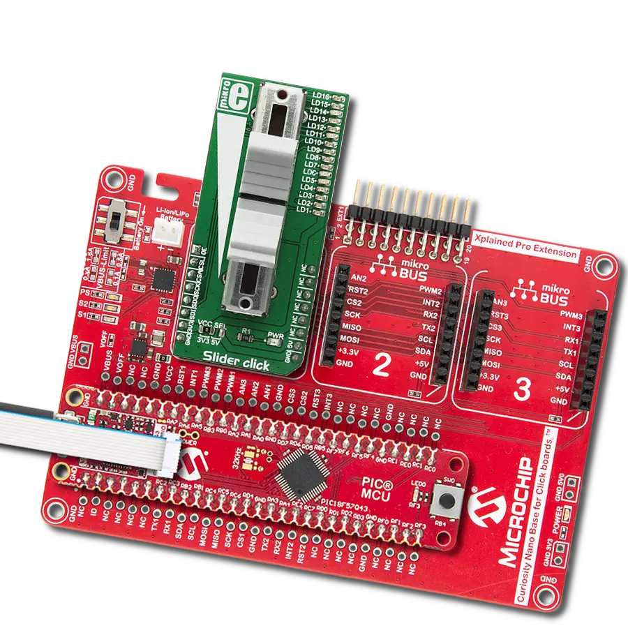
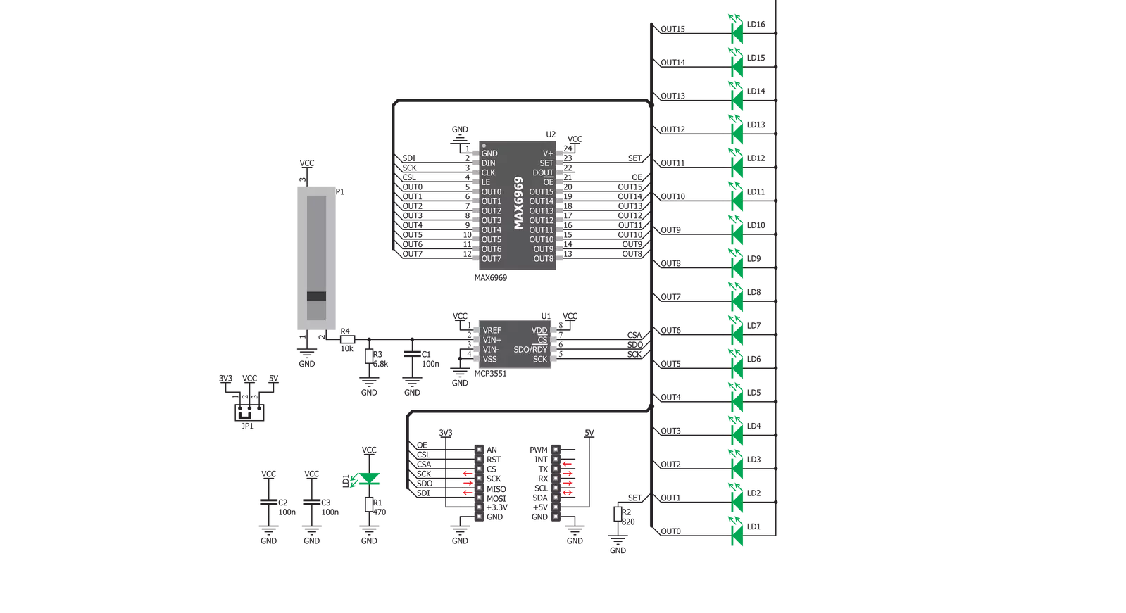
Slider Click is based on two sections: the first section is the slider section itself, with the sliding potentiometer end terminals connected between GND and the VCC, and the wiper connected to the MCP3551 IC, which is a low-power, single-channel 22-bit delta-sigma ADC from Microchip. The slider acts as a voltage divider so that the voltage between the GND and the wiper position is determined by the slider position. This voltage is then applied to the input pin of the 22bit ADC converter and converted to a digital value. The MCP3551 has its SPI lines routed to the mikroBUS™ so that the values can be read easily
by the MCU. The second section of this Click board™ consists of the MAX6969, a well know 16-port, constant-current LED driver from Maxim Integrated, used to control the SMD LEDs. The MAX6969 IC uses the same SPI lines as the ADC, but to avoid data collision, different chip select (CS) line is used. While the ADC uses the CS line routed to the CS pin of the mikroBUS™, the LED driver uses the RST line of the mikroBUS™ as the chip select input. This allows to work with both ICs independently. MAX6969 output enable (OE) pin is routed to the AN pin of the mikroBUS™, making it easy to completely turn off the output stage
of the MAX6969, by setting this pin to a HIGH logic state. If left floating, this pin will be pulled down to the GND by the 10K resistor. The output LED current is constant and it is set to around 20mA by the resistor on the SET pin of the MAX6969. This Click board™ can operate with either 3.3V or 5V logic voltage levels selected via the VCC SEL jumper. This way, both 3.3V and 5V capable MCUs can use the communication lines properly. Also, this Click board™ comes equipped with a library containing easy-to-use functions and an example code that can be used as a reference for further development.


Features overview
Development board
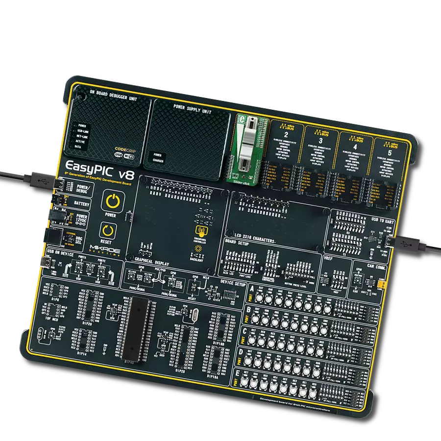
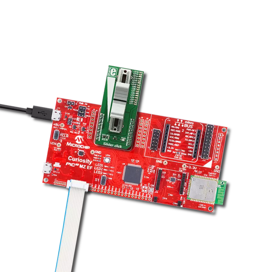
Curiosity PIC32 MZ EF development board is a fully integrated 32-bit development platform featuring the high-performance PIC32MZ EF Series (PIC32MZ2048EFM) that has a 2MB Flash, 512KB RAM, integrated FPU, Crypto accelerator, and excellent connectivity options. It includes an integrated programmer and debugger, requiring no additional hardware. Users can expand
functionality through MIKROE mikroBUS™ Click™ adapter boards, add Ethernet connectivity with the Microchip PHY daughter board, add WiFi connectivity capability using the Microchip expansions boards, and add audio input and output capability with Microchip audio daughter boards. These boards are fully integrated into PIC32’s powerful software framework, MPLAB Harmony,
which provides a flexible and modular interface to application development a rich set of inter-operable software stacks (TCP-IP, USB), and easy-to-use features. The Curiosity PIC32 MZ EF development board offers expansion capabilities making it an excellent choice for a rapid prototyping board in Connectivity, IOT, and general-purpose applications.

Microcontroller Overview
MCU Card / MCU

Architecture
PIC32
MCU Memory (KB)
2048
Silicon Vendor
Microchip
Pin count
100
RAM (Bytes)
524288
Used MCU Pins
mikroBUS™ mapper
Take a closer look
Click board™ Schematic
Step by step
Project assembly

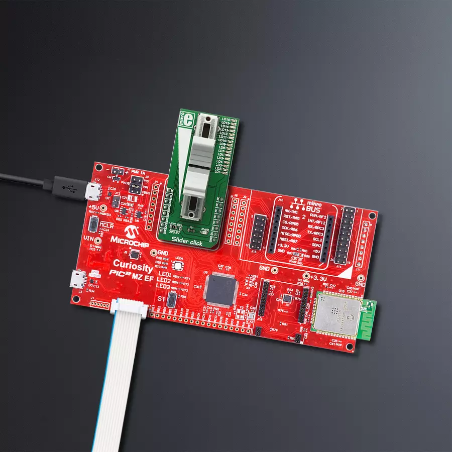
Start by selecting your development board and Click board™. Begin with the Curiosity PIC32 MZ EF as your development board.


Software Support
Library Description
This library contains API for Slider Click driver.
Key functions:
slider_read_adc_and_ready- Function calls slider_readADC function, but first checks is ADC conversion finishedslider_enable_led_output- Function enables LED output to shows output laches when state is low, and disables LED output when state is highslider_enable_output_laches- Function enables output laches to monitor converted ADC value, when state is high
Open Source
Code example
The complete application code and a ready-to-use project are available through the NECTO Studio Package Manager for direct installation in the NECTO Studio. The application code can also be found on the MIKROE GitHub account.
/*!
 * \file
 * \brief Slider Click example
 *
 * # Description
 * This example detect even the smallest move, faithfully capturing the smoothness of
 * the slider movement, while digitizing its position.
 *
 * The demo application is composed of two sections :
 *
 * ## Application Init
 * Initializes Click driver
 *
 * ## Application Task
 * Converts analog input voltage (VCC), witch value depends on the slider position,
 * to digital output value, shows result of conversion on LED and logs result on USB UART.
 *
 *
 * \author MikroE Team
 *
 */
// ------------------------------------------------------------------- INCLUDES

#include "board.h"
#include "log.h"
#include "slider.h"

// ------------------------------------------------------------------ VARIABLES

static slider_t slider;
static log_t logger;

static float adc_value;

// ------------------------------------------------------ APPLICATION FUNCTIONS

void application_init ( void )
{
    log_cfg_t log_cfg;
    slider_cfg_t cfg;

    /**
     * Logger initialization.
     * Default baud rate: 115200
     * Default log level: LOG_LEVEL_DEBUG
     * @note If USB_UART_RX and USB_UART_TX
     * are defined as HAL_PIN_NC, you will
     * need to define them manually for log to work.
     * See @b LOG_MAP_USB_UART macro definition for detailed explanation.
     */
    LOG_MAP_USB_UART( log_cfg );
    log_init( &logger, &log_cfg );
    log_info( &logger, "---- Application Init ----" );

    //  Click initialization.

    slider_cfg_setup( &cfg );
    SLIDER_MAP_MIKROBUS( cfg, MIKROBUS_1 );
    slider_init( &slider, &cfg );
    Delay_ms ( 200 );

}

void application_task ( void )
{
    adc_value = slider_write_output( &slider );
    log_printf( &logger, "%.2f\r\n", adc_value );
    Delay_ms ( 100 );
}

int main ( void )
{
    /* Do not remove this line or clock might not be set correctly. */
    #ifdef PREINIT_SUPPORTED
    preinit();
    #endif

    application_init( );

    for ( ; ; )
    {
        application_task( );
    }

    return 0;
}


// ------------------------------------------------------------------------ END
Additional Support
Resources
Category:Potentiometers